Micropiles occupy a very specific niche in Victorian piling: everything that can’t be done by a full-sized rig. Inside a 2.1 m crawl space. Through a reinforced concrete slab without cutting it. Next to a heritage wall on a live railway easement. Carrying a 600 kN column load in a 300 × 300 mm structural footprint.
Every micropile job is, in essence, a retrofit. Someone has decided — rightly — that the existing foundations are inadequate for a new load case, and now the ground has to be upgraded from inside the existing structure. This guide covers how we design, install and test micropiles in Melbourne conditions.
What is a micropile, strictly speaking?
The term is used loosely in practice, but the original Federal Highway Administration (FHWA) definition is useful: a micropile is a small-diameter (typically 150–300 mm), high-capacity (typically 200–1,500 kN working load) bored pile, usually with a central steel reinforcement that can carry a significant share of the load in compression and all of the load in tension, and installed using small-scale drilling equipment capable of working in confined spaces.
In Australia, the equivalent term is often “mini-pile” or “bar pile”. AS 2159:2009 does not have a separate chapter on micropiles — the general design framework applies, but the detailing is dominated by steel (AS 3679.1 / AS 3679.2 bars or casing) rather than concrete.
Typical Melbourne micropile configurations are:
- Type A (bar-reinforced, gravity-grouted): 150–200 mm diameter, 30–40 mm (or larger) thread-bar central reinforcement, gravity-placed cement grout. Capacity governed by grout-ground bond. Working loads 150–400 kN typical.
- Type B (bar + pressure-grouted): As Type A, but grout is injected under pressure (typically 0.5–1.0 MPa) on the return stroke of the drill casing. The pressure locally increases ground stress around the pile, boosting skin friction by 30–80% in granular soils. Working loads 300–800 kN.
- Type D (permanently-cased): 200–300 mm steel casing left in place, bar or cage reinforcement inside, grout-filled. Used where corrosion allowance is significant or where the casing contributes to compression capacity. Working loads 500–1,500 kN.
When you actually need micropiles
Micropiles are not cheap per pile. A 150 mm × 10 m Type A micropile costs roughly 3–5× as much per cubic metre of ground improved as a 450 mm bored pier. You specify micropiles when the alternative is “can’t be done”:
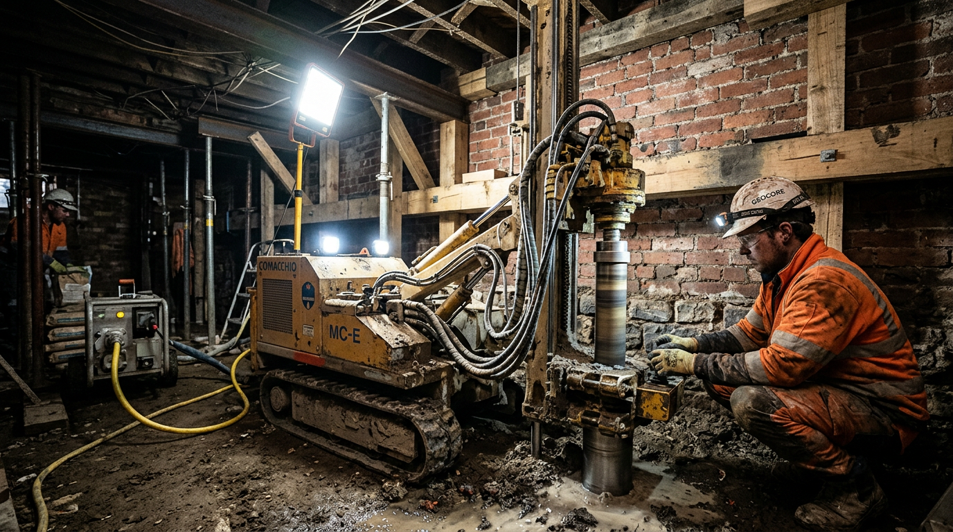
- Underpinning an existing footing with sub-500 mm headroom. Compact rigs reach 2.0 m overall height.
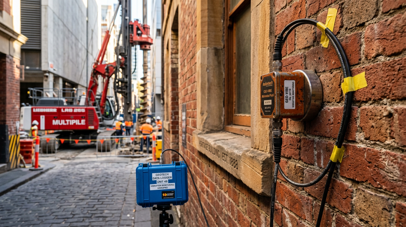
- Load increase on a heritage structure where vibration-based methods are prohibited.
- Retrofits through existing floor slabs — the rig sets up, drills straight through a 200 mm slab, installs the pile, and the slab is re-jointed.
- Live-plant piling inside operating industrial facilities, substations, switch rooms — where the machinery cannot be de-energised.
- Very poor access rail corridors, narrow laneways, interior courtyards.
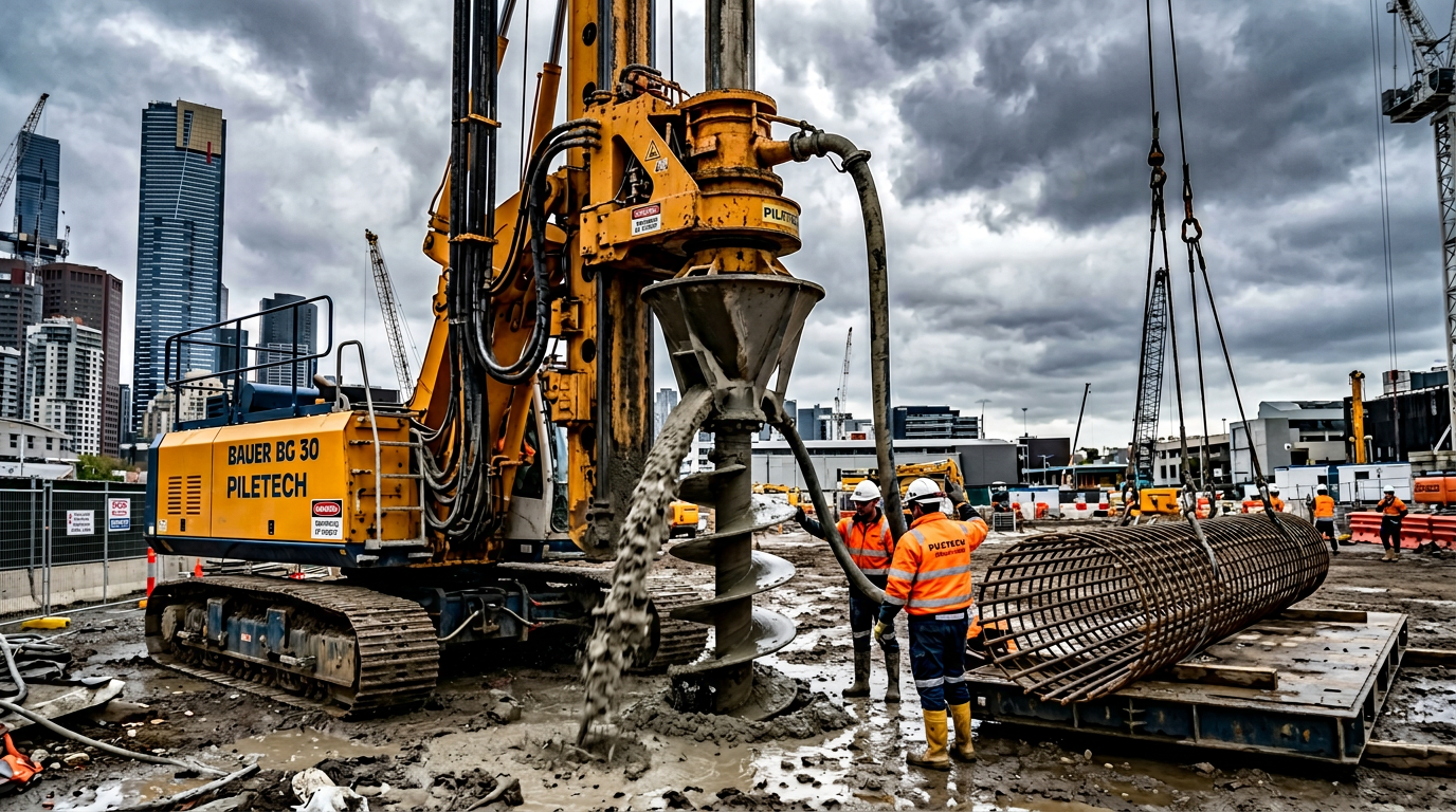
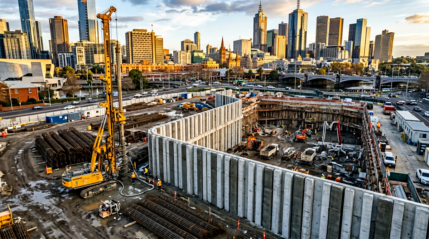
For greenfield civil jobs or normal commercial new-builds, micropiles are almost never the economical answer. A full-sized bored pier or CFA pile beats them every time (see our bored vs screw piles article for the broader decision tree).
Design — capacity from grout-ground bond
Unlike concrete bored piers where capacity is dominated by end-bearing on a competent founding stratum, micropile capacity is almost entirely a shaft-friction game. Toe capacity on a 150 mm diameter is trivial. What matters is the bond between the grout and the soil or rock along the full bonded length.
AS 2159 Table 4.3 and 4.4 give generic shaft friction coefficients but the FHWA document Reference Manual for Micropile Design and Construction (FHWA-NHI-05-039) gives much more useful ground-specific grout-ground bond stress values:
| Ground | Typical α_bond (Type A) | Typical α_bond (Type B, pressure-grouted) |
|---|---|---|
| Soft clay | 35–70 kPa | 70–150 kPa |
| Stiff clay | 70–135 kPa | 100–180 kPa |
| Medium-dense sand | 70–140 kPa | 170–300 kPa |
| Dense sand | 100–190 kPa | 300–500 kPa |
| Weathered rock (Silurian Melbourne siltstone) | 300–1,000 kPa | 700–1,700 kPa |
| Fresh rock (Melbourne basalt) | 700–1,700 kPa | 1,000–2,500 kPa |
The design capacity of the pile is typically governed by either:
- Grout-ground bond (the number above, × bonded perimeter × bonded length), or
- Steel bar strength (limit state capacity of the thread bar per AS 3600 / AS 4671),
- Grout column compression (f’c × gross area × strength reduction factor).
On short bonded lengths in good rock, (1) does not govern — the steel does. On long bonded lengths in weak soils, (1) governs. Part of good design is picking the bonded length that makes these two equal.
Installation — what we actually do
On a typical Melbourne underpinning job with 2.0 m headroom and a 300 kN working load:
- Set up the compact rig. Track-mounted drill, mast folds to 1.8 m. A smaller hydraulic crawler rig can handle 1.6 m crawl spaces. Diamond-drill the slab if going through.
- Drill with temporary casing. 200 mm casing with inner rotary tooling. Spoil is flushed back to surface with water or air-water mist. On contaminated sites, water+polymer with capture tank.
- Verify founding. Continuous record of penetration rate, rotary pressure and flush return. For rock-socket piles, a spot inspection of flush returns for rock fragments.
- Place the bar and grout. Central Macalloy 1080 or equivalent bar with centralisers every 2–3 m. Tremie-pipe grout from the toe upwards, displacing flushwater. Typical grout mix 0.40 w/c, 50–60 MPa at 28 days, neat cement + superplasticiser.
- For Type B: withdraw casing in steps with grout pressure applied through a packer. Typically 0.5–1.0 MPa.
- Trim and cap. Cut bar to design stick-up, encapsulate in a cementitious protection medium, detail into the new pile cap or transfer beam above.
A typical output on a good day: 4–8 micropiles at 10–12 m length, two-rig spread. On a bad day: the cellar collapses and you find unexpected rubble fill.
Load testing — mandatory, always
AS 2159 Clause 5.4 testing provisions apply to micropiles. On small underpinning projects, a static load test on at least one sacrificial pile is almost always specified. The typical scope:
- One proof test on a production pile to 150% of design working load (SLS check).
- One sacrificial test to 250% of design working load (ULS check). Pile destroyed in the process; reaction from adjacent working piles.
- Instrumentation — dial gauges at pile head for deflection; strain gauges along the shaft on the sacrificial pile if load distribution is important to the design.
On micropiles working in tension (tie-downs, uplift anchors), pull-out tests are the norm rather than compression. Bond stress is often lower in tension than compression by a factor of 0.7–0.9.
Common mistakes we fix on arrival
- Under-estimating the bonded length. Designers use full pile length as bonded length, rather than the length in competent ground. Always distinguish “free length” (loose fill, not contributing) from “bonded length” (competent ground).
- Specifying bar diameter without checking grout column capacity. A 50 mm bar is useless in a 150 mm pile at 60 MPa grout — the grout column fails first.
- Ignoring corrosion. Underground micropiles in reactive soils need a corrosion allowance. AS/NZS 2312 and AS 4100 guidance applies. Epoxy coating, sacrificial thickness, or permanent casing all work.
- No allowance for group effects. Close-spaced micropile groups (spacing < 3d) need an efficiency reduction — same as any other pile group. See our pile group efficiency article.
- No temporary propping during underpinning sequence. Excavating under a live footing without a shoring plan has killed people. Always engineer the propping sequence before the first pile is drilled.
References
- Standards Australia, AS 2159:2009 Piling — Design and Installation.
- Federal Highway Administration, Reference Manual for Micropile Design and Construction, FHWA-NHI-05-039, 2005.
- International Society for Micropiles, State of the Practice Report, 2015.
- Bruce D.A., Micropiles: State of Practice, DFI 37th Annual Conference, 2012.
VIC PILING is a specialist piling contractor delivering tier-1 civil, energy, rail and commercial foundations across Victoria since 2016. Our principals bring 30+ years of combined design, installation and compliance experience under AS 2159, AS 5100 and AS 4678.