Continuous Flight Auger (CFA) piling quietly became the dominant replacement-pile method in metropolitan Australia somewhere around the mid-2000s. It is fast, largely vibration-free, produces minimal spoil on the surface relative to a bored pier, and — critically — it installs a support fluid (concrete) the moment the auger withdraws, which means the hole is never unsupported. For Melbourne’s reactive clays and water-bearing granular fills, that matters.
But CFA is also the pile type most vulnerable to sloppy execution. Get the concrete pressure wrong, over-auger, pull the auger too fast, or allow the cage to hang up, and you end up with a pile that looks fine on the concrete dockets and fails on a Cross-Hole Sonic Logging (CSL) test. This article sets out what a good CFA pile looks like, and what a competent specification should demand.
How the method actually works
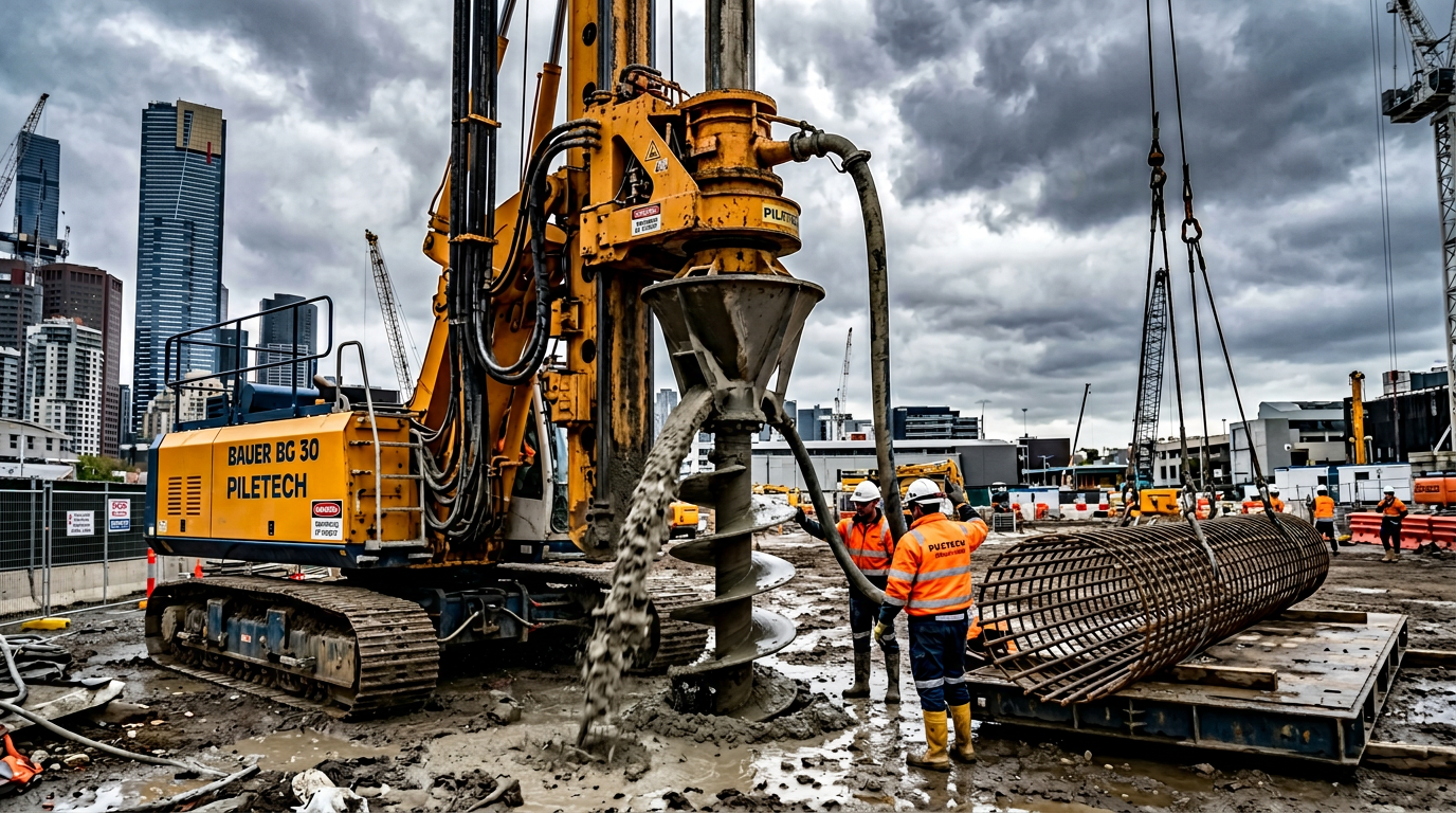
A CFA pile is installed in four overlapping steps, all of which happen without the auger ever fully leaving the ground:
- Advancement. A hollow-stem auger is rotated into the ground at a rate that roughly matches the rate of advance. The flights carry cuttings up to the surface while the soil below is pushed aside rather than brought up wholesale. Over-rotation (spinning the auger at a fixed depth) is a cardinal sin — it “mines” soil from the sides and creates a stress-relieved zone.
- Concreting on withdrawal. When the design depth is reached, high-slump concrete (typically 180–220 mm slump, 32–40 MPa, small-aggregate mix) is pumped down the hollow stem under positive pressure. The auger is withdrawn at a rate slower than the rate of concrete delivery so the bore is always filled, never pumped into air.
- Cage installation. Immediately on completion of concreting, a prefabricated reinforcement cage is lowered into the wet concrete. For piles up to about 15 m and with a sensible cage mass, gravity alone is enough; deeper cages or stiffer concrete may need vibration or a slight push from the rig.
- Trim and protect. The pile top is trimmed to design cut-off, reinforcement protected, and the next pile commenced.
AS 2159:2009 Piling — Design and Installation classifies CFA piles as replacement piles under Clause 3.2. The capacity framework in Section 4 (ultimate geotechnical strength) and the installation requirements in Section 6 both apply without modification.
When to specify CFA
CFA piling sits in a competitive middle ground. It is typically the right answer when:
- Loads are moderate-to-heavy. Typical CFA diameters run 450–900 mm in Melbourne, to depths of 25–30 m. Working loads of 1,500–5,000 kN per pile are routine. Beyond that, a full bored pier with temporary casing is often more economical.
- Ground is cohesive or dense granular. Stiff clays, sandy clays and medium-dense-or-better sands are ideal. The hole wall is held by the flights above and the concrete below at all times, so short-term stability is not required.
- Vibration matters. CFA is effectively vibration-free compared to driven piles. For sites close to heritage masonry, live railways, hospitals or instrumented tenants, CFA often wins purely on this count. See our article on vibration limits and heritage buildings for the limits that tend to govern.
- Production rate matters. An experienced crew with a modern rig can install 15–25 piles per day at 15 m depth in competent Melbourne clay. That is two to three times the rate of a cased bored pier crew.
When CFA is the wrong call
CFA is a poor choice — sometimes a dangerous one — in a handful of ground and project conditions:
- Running sands below the water table. Loose, clean, saturated sands can flow up the auger during advancement. The pile hole may look fine from the surface while sand has already entered the bore. Without a tremie concrete seal at the toe, you can end up with a pile that has a loose granular collar at depth. Either switch to a cased rotary pile or specify temporary casing through the granular zone.
- Very soft clays (undrained shear strength < 25 kPa). Soft clay does not hold the auger flights. The flights act like a screw and the pile fabrication fails. Displacement piles (driven, screw or DEWP) are a better fit.
- Rock-founded piles with hard sockets. CFA augers cannot cut rock effectively. If the design requires a 3 m socket into Silurian siltstone or basalt, a rotary rig with rock tooling is needed. Bored piers with down-hole hammers or rock augers are the right answer. See our article on rock socketing in Victorian basalt and granite.
- Piles longer than the auger. Typical CFA augers are 20–28 m. Piles longer than the auger require extension techniques (oscillating rig or rotary Kelly) that erode CFA’s advantage.
- Contaminated spoil. CFA throws all spoil to the surface. On contaminated fill sites, spoil handling can dominate the cost equation.
The quality-control instrumentation no spec should be without
Every modern CFA rig in Australia carries real-time instrumentation on the mast. A compliant CFA specification should demand the printed log for every production pile, and should nominate acceptance criteria for:
| Parameter | Typical acceptance criterion | Why it matters |
|---|---|---|
| Torque vs depth | Continuous, no sudden drops; matches expected stratigraphy | Torque drop = cavity, soft zone, or the auger spinning in air |
| Crowd / penetration rate | ≤ 2.0 m/min into cohesive soil | Faster rates over-auger — stress-relieves the soil beside the pile |
| Concrete pressure at base | ≥ 50 kPa (typical spec: 50–100 kPa) | Confirms the concrete arrives under positive head, not gravity alone |
| Concrete overbreak volume | ≥ 100% of theoretical (typically 105–115% on first pour) | Under-break = voids; extreme over-break = cavity or over-auger |
| Auger withdrawal rate | Matched to concrete volume curve | De-coupling of the two curves is the single clearest indicator of a defect |
| Concrete volume per metre | Plotted against pile length | Flat or declining volume curve at the pile toe = defect zone |
The industry-standard output is a “concrete vs depth” plot shown against “theoretical shaft volume vs depth”. A healthy pile shows the actual line running consistently above and parallel to the theoretical. Flat sections, spikes or crossovers should be flagged immediately.
CSL (Cross-Hole Sonic Logging, typically to ASTM D6760) is the appropriate integrity test for CFA piles on tier-1 projects, particularly where the pile is a primary load path. Design teams should allow for four CSL tubes on piles ≥ 900 mm diameter, three tubes on 600–750 mm, and at least one tube (low-strain integrity testing per ASTM D5882) on smaller piles.
Design notes engineers often miss
A handful of detailing issues crop up on CFA projects time after time:
- Cage stick-up. Minimum 500 mm of cage above cut-off, with proper tie-back into the pile cap. Without adequate stick-up the cap anchorage fails under AS 3600 Section 13 — see pile-to-pilecap connection.
- Cage roller spacers. Always specify roller (not plastic chair) spacers on CFA. The cage is being pushed through wet concrete, not placed in a dry hole. Chairs fold over and break off.
- Cage mass vs concrete slump. A 12 m cage at 50 kg/m will generally self-weight install; longer cages or lighter cage weights may need vibration. Design the cage with vibration holes if depth exceeds 18 m.
- Temperature and slump retention. Melbourne’s CFA season peaks in November through March. At 30°C ambient, slump can drop from 210 mm at batch to 140 mm by the time the auger reaches 20 m. Specify a retarder and the delivery time limit.
How we price CFA work
VIC PILING runs CFA in the 450–900 mm range daily across Victoria. We price CFA on three line items: pile metres (the biggest line), mobilisation (rig-dependent), and QA pack (instrumentation printouts, concrete test cubes, CSL where applicable). For a typical tier-1 civil or commercial job — 40–120 piles, 600 mm at 20 m — we will usually turn a detailed quote around in 48 business hours from drawings. See our guide to piling cost in Victoria for 2026 for the numbers behind each line item.
References
- Standards Australia, AS 2159:2009 Piling — Design and Installation.
- Fleming W.G.K., Weltman A.J., Randolph M.F., Elson W.K., Piling Engineering, 3rd ed., Taylor & Francis, 2009 (Chapter 6 on CFA).
- Federation of Piling Specialists (UK), Handbook on Pile Load Testing, 2006.
- ASTM D6760 / AS 2159 Section 7, Cross-Hole Sonic Logging for drilled shafts.
VIC PILING is a specialist piling contractor delivering tier-1 civil, energy, rail and commercial foundations across Victoria since 2016. Our principals bring 30+ years of combined design, installation and compliance experience under AS 2159, AS 5100 and AS 4678.