Every structural engineer who has signed off a pile cap has done the axial-compression check in their sleep. A cap is a deep beam; piles are the supports; the cap takes the column load and distributes it to the piles. Easy.
Then the engineer gets a post-install photo showing the pile cages 200 mm short of the specified stick-up, and the whole load-path assumption falls apart. The cap isn’t connected to the piles the way the drawings say. The connection, not the cap, is what gets rejected at certification.
This article walks through the correct AS 3600 anchorage design for pile-to-pilecap connections, the common detailing mistakes, and the constructability rules that make sure the as-built matches the design.
What the connection actually needs to do
The pile-to-pilecap connection is a moment connection in compression and tension. Under normal service:
- Compression — column load plus cap self-weight passes down through the cap, into the pile cages, into the pile shafts. The reinforcement transfers load through the bond over the embedment length.
- Moment — any applied moment at the column base (fixed-base column, for instance) is resisted by differential compression/tension at the piles in the cap. One side pushes, the other pulls.
- Shear — horizontal loads (wind, seismic) introduce shear at the pile head and moment some distance into the pile.
- Tension (uplift) — for towers, transmission structures or seismic load cases, the pile may be in net tension. The cages must transfer the tensile load through the cap-pile interface.
Each of these load paths depends on the reinforcement cage extending far enough into the cap, with full anchorage.
The four code requirements
1. Stick-up length (AS 3600 Clause 13.1.5)
The pile cage must extend into the cap a minimum of the development length (L_sy.tb) of the pile reinforcement, rounded up to a structural thickness. In practice:
- 500 mm minimum for pile cap depths ≤ 800 mm.
- Full development length for larger caps — typically 600–900 mm for N24–N32 bars at 40 MPa concrete.
Engineering rule of thumb: design the cage with 750 mm stick-up for all piles ≥ 600 mm diameter. This handles most practical cap depths.
2. Bar development length (AS 3600 Clause 13.1)
AS 3600 gives the bonded development length of a reinforcement bar as:
L_sy.tb = (0.5 × k_1 × k_3 × f_sy / √f'_c) × d_b × k_4 × k_5 ≥ 29 × k_1 × d_b
For typical N24 bars, f’_c = 40 MPa, cover = 50 mm, bar spacing ≥ 3d_b:
- L_sy.tb ≈ 720 mm for bars in tension (upper pile region).
- Lap length (L_sy.tb.lap) = L_sy.tb × k_7 where k_7 = 1.0–1.4 depending on lap condition.
The cage stick-up must provide for the full lap with the cap reinforcement above. If the cap reinforcement and the pile reinforcement don’t lap cleanly, the connection fails.
3. Spalling reinforcement (AS 3600 Clause 13.1.5 commentary)
At the pile head, a bursting / spalling force develops in the concrete immediately above the pile, caused by the concentrated compressive load spreading out into the cap. If you’ve ever seen a pile cap with a ring crack at the top of each pile head at about 100 mm depth, that’s spalling.
Control this with:
- A horizontal “ring” reinforcement at the top of the pile — typically 3 × R12 rings spaced at 75 mm, tied to the pile longitudinal bars.
- Cap reinforcement extending beyond each pile diameter by at least the pile diameter in each direction.
4. Strut-and-tie check (AS 3600 Chapter 12)
For pile caps, strut-and-tie is the correct model. The column load “flows” down to each pile via concrete struts (compression) and horizontal ties (tension) at the cap’s lower face.
- Strut angle from column face to pile centre — should be 45°–60° for the cap to behave as a deep beam. Flatter angles require more tension reinforcement and increase cap depth.
- Ties at the cap soffit — full development length past each pile face in both directions.
- Node check at each pile head — bearing stress on node face vs AS 3600 Clause 12.4.
Most standard cap sizing (2-pile, 3-pile, 4-pile) has pre-computed designs in the Concrete Institute of Australia’s Reinforced Concrete Design Handbook and similar references. Always check the specific project’s strut angle against these defaults.
The practical cage detail
A proper pile cage for a 900 mm diameter pile with 4 × N32 main bars might look like:
┌─────────────────┐   ← top of pile cage, 750 mm stick-up above pile cut-off
│  4 × N32        │
│  longitudinal   │
│  bars           │
│                 │
│ R12 spiral      │   ← 75 mm pitch in top 3d and bottom 3d
│ at 75 mm pitch  │      150 mm pitch in middle portion
│                 │
│                 │
├─────────────────┤   ← pile cut-off (nominal)
│                 │
│  remainder of   │
│  cage in pile   │
│                 │
└─────────────────┘   ← bottom of pile, typically 150 mm above toe
Key numbers:
- Cover — 75 mm minimum in pile, 50 mm minimum in cap above cut-off (AS 3600 Table 4.10.3.2).
- Lap positions — stagger laps by 0.5 × L_sy.tb apart; never put all laps at the same level.
- Transverse ties — required at 150 mm max pitch in the “disturbed region” at the pile head (1d above cut-off).
- Roller spacers — plastic circular spacers at 2 m pitch, rated to withstand concrete pressure during placement.
Constructability — where it goes wrong
Wrong: Pile cages cut short on site
“The cage is a bit long — trim it to fit the cap depth.” Never acceptable. The cage is designed for its full length. Cut it, you destroy the anchorage. If the as-cast cut-off is too high for the cap, either raise the cap or extend the cage with mechanical splices.
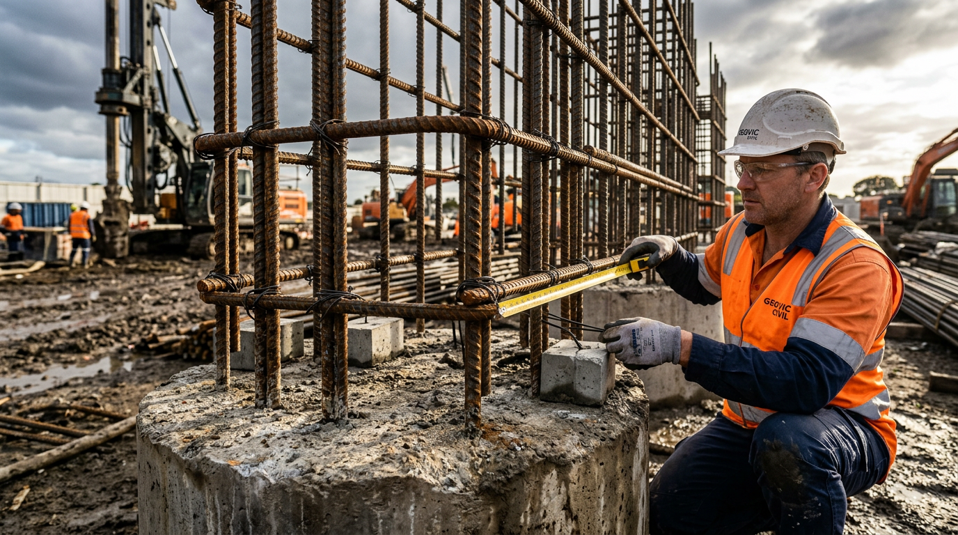
Wrong: Pile mis-located, main bars clashing with cap reinforcement
Each pile’s main bars should align with the cap reinforcement orientation — ideally, main bars on the cap’s orthogonal axes. Positional tolerance is typically ±75 mm for the pile centreline. If the pile ends up out-of-tolerance, local redesign of the cap reinforcement pattern may be required.
Wrong: Pile cut-off below design, exposing cage below cover
Pile is over-dug, cut-off ends up below design. Exposed rebar has insufficient cover; corrosion ensues. Fix: remove concrete to clean steel, apply corrosion protection (epoxy or cementitious), re-encapsulate in the new cap concrete. Costs money; always cheaper than re-piling.
Wrong: No spalling reinforcement at pile head
Drawings show main cage only; no ring reinforcement at the top. Pile cap cracks ring around each pile head under early service load. Result: hairline cracks (cosmetic but documented) or worse (reinforcement corrosion). Always specify the ring.
Wrong: Cage rolled into hole without centralisers
Cage contacts the side of the excavation; cover deficient on that face. Visible on post-cast CSL or visual inspection. Always specify roller centralisers, 2 m pitch minimum.
What we do at VIC PILING
On every tier-1 project, our engineering cell delivers a cage cut-list with:
- Bar sizes and lengths — full detail in a fabrication schedule.
- Lap staggers — plan + section showing lap positions.
- Spalling reinforcement — ring detail at pile head with bar sizes, spacing, tie requirements.
- Tolerance diagram — showing setout tolerance and the resulting cage alignment in the cap.
- Pour sequence — concrete placement plan around the cage, including vibration locations.
- Certification cover sheet — engineer’s signature against the AS 3600 / AS 2159 cross-check.
This document is what the principal contractor’s engineer signs against. It is also what closes out the AS 2159 Clause 6 construction records on completion.
References
- Standards Australia, AS 3600:2018 Concrete Structures, Chapters 12 (strut-and-tie) and 13 (anchorage and lap splices).
- Standards Australia, AS 2159:2009 Piling — Design and Installation, Section 6 (installation) and 7 (records).
- Concrete Institute of Australia, Reinforced Concrete Design Handbook, 8th ed., 2021.
- Schlaich J., Schäfer K., Jennewein M., Toward a Consistent Design of Structural Concrete, PCI Journal, 1987 — the foundational strut-and-tie paper.
- Park R., Paulay T., Reinforced Concrete Structures, Wiley, 1975 — the classic text on detailing.
VIC PILING is a specialist piling contractor delivering tier-1 civil, energy, rail and commercial foundations across Victoria since 2016. Our principals bring 30+ years of combined design, installation and compliance experience under AS 2159, AS 5100 and AS 4678.