Every civil-engineering student meets these equations in an undergraduate foundations course and forgets them by graduation. Which is unfortunate, because on every piling project you’ll ever design, one of the three methods below is sitting behind the capacity number in the geotech report.
This article is the tutorial your lecturer should have given you. We walk through the α-method, β-method and λ-method for pile shaft friction in cohesive soil — what they mean physically, what numbers to use, and how to choose between them on a Victorian job.
The three methods in one line each
- α-method (Tomlinson 1957, 1971): unit shaft friction = α × c_u. Total-stress. Best for stiff to very stiff clays.
- β-method (Meyerhof 1976, Burland 1973): unit shaft friction = β × σ’_v. Effective-stress. Best for soft to medium clays and long-term (drained) conditions.
- λ-method (Vijayvergiya & Focht 1972): unit shaft friction = λ × (σ’_v + 2·c_u). Hybrid. Originally calibrated for long offshore piles.
They are all empirical. All of them are calibrated against instrumented full-scale pile tests — mostly in the Gulf of Mexico, North Sea and a handful of onshore sites. None of them is “correct” — they are three competing ways of fitting a curve to a messy data set.
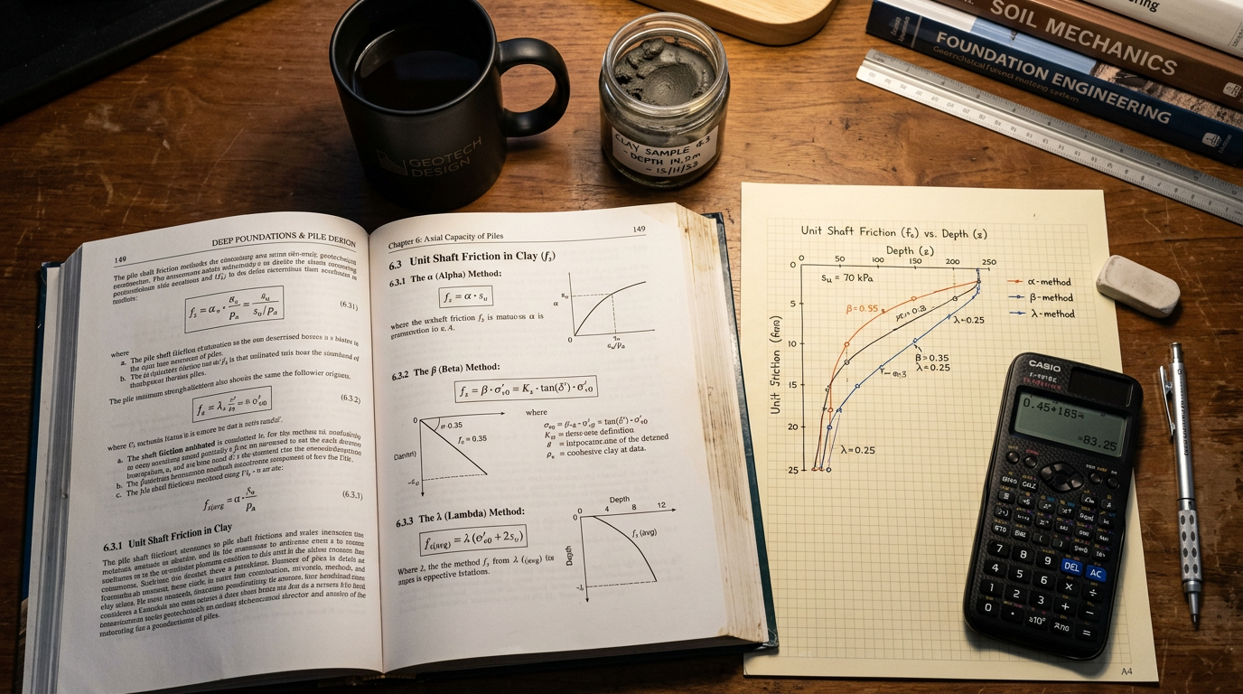
The α-method
Physical basis: shaft friction = adhesion between pile and soil ≈ α × undrained shear strength, where α accounts for soil disturbance, remoulding, and pile-soil interface behaviour during installation.
Tomlinson’s original α chart (1957) was a plot of α vs c_u/p’_a for driven piles in stiff clay. The curve starts at α ≈ 1.0 for very soft clay (c_u ~25 kPa) and drops to α ≈ 0.3 for very stiff clay (c_u > 200 kPa). The drop reflects the fact that very stiff clay doesn’t remould uniformly around the pile — gaps form, and less shaft contact area is mobilised.
Modern design uses the API RP 2A-WSD (2000) formulation:
α = 0.5 × ψ^(-0.5) for ψ ≤ 1.0
α = 0.5 × ψ^(-0.25) for ψ > 1.0
where ψ = c_u / σ’_v at the depth of interest.
Typical values on Victorian clays:
| Soil | c_u (kPa) | σ’_v (kPa) | ψ | α |
|---|---|---|---|---|
| Soft Melbourne alluvial clay | 30 | 60 | 0.5 | 0.70 |
| Medium stiff Coode Island silt | 70 | 120 | 0.58 | 0.66 |
| Stiff Brighton Group clay | 150 | 200 | 0.75 | 0.58 |
| Very stiff Silurian-derived clay | 250 | 300 | 0.83 | 0.55 |
Strengths of the α-method:
- Direct — c_u is what the geotech report gives you most reliably.
- Well-calibrated for typical stiff-clay driven-pile cases.
- Standard in AS 2159 and API codes.
Weaknesses:
- Assumes undrained (short-term) behaviour — not valid long-term for soft clays where pore pressures dissipate and capacity changes.
- α values have large scatter — actual α can vary by ±30% for nominally identical clay.
- Not appropriate for very long piles where the average c_u is poorly represented by a single value.
The β-method
Physical basis: pile shaft friction is a frictional problem at the pile-soil interface, governed by effective stress — not by undrained shear strength.
f_s = K_s × σ'_v × tan(δ) = β × σ'_v
where K_s is a coefficient of horizontal earth pressure against the pile (typically 0.7–1.2 for driven piles, 0.5–0.8 for bored), σ’_v is vertical effective stress, and δ is the pile-soil interface friction angle (typically 20–30°).
The β-method gives you values that grow linearly with depth (because σ’_v grows with depth). This is physically more realistic for long piles than the α-method, where unit friction tracks c_u (which often doesn’t grow much with depth).
Typical β values on Victorian sites:
| Soil | Pile type | β |
|---|---|---|
| Soft clay | Bored | 0.20–0.30 |
| Soft clay | Driven | 0.25–0.40 |
| Stiff clay | Bored | 0.15–0.25 |
| Stiff clay | Driven | 0.25–0.35 |
| Loose sand | Driven | 0.25–0.40 |
| Medium-dense sand | Driven | 0.40–0.80 |
| Dense sand | Driven | 0.80–1.50 |
Strengths:
- Physically based (Coulomb friction).
- Natural fit for long-term (drained) analysis.
- The only sensible method in sand (no meaningful c_u exists).
- Directly usable for downdrag analysis — see our negative skin friction article.
Weaknesses:
- Requires you to estimate K_s, which varies with pile type, installation method, and overconsolidation ratio — another source of scatter.
- Underestimates shaft friction at shallow depths where effective stress is low but adhesion can still be significant.
The λ-method
Vijayvergiya & Focht (1972) observed that for very long offshore piles, neither α nor β alone fit the data. They proposed a hybrid:
f_s_avg = λ × (σ'_v_avg + 2 × c_u_avg)
where the averaging is over the full pile length, not depth-by-depth. λ is a dimensionless coefficient that varies with pile length:
| Pile length (m) | λ |
|---|---|
| 0–10 | 0.50 |
| 10–20 | 0.36 |
| 20–30 | 0.27 |
| 30–40 | 0.22 |
| 40–60 | 0.17 |
| >60 | 0.14 |
The λ-method was calibrated on very long (30–100 m) steel pipe piles in the Gulf of Mexico. It captures a known effect — that average unit friction declines with length — that neither α nor β does well.
Strengths:
- Fits long offshore pile data better than α or β.
- Gives a single answer for the whole pile (useful for preliminary sizing).
Weaknesses:
- Averages over the pile length — loses depth-distribution information needed for downdrag, anchor segment design, or cyclic load analysis.
- Calibrated outside typical onshore Victorian conditions.
- Rare in Australian practice except for deep steel piles in marine projects.
Which method to use on a Victorian job
We use a simple decision tree:
- Short bored pier (< 15 m) in stiff-to-very-stiff clay → α-method. Straightforward, direct.
- Long driven pile (> 20 m) in soft-to-medium clay or mixed profile → β-method. Handles increasing effective stress with depth.
- Pile subject to downdrag → β-method (mandatory for consolidation analysis).
- Pile in sand → β-method (no meaningful c_u).
- Very long marine pile (> 40 m) → check λ in addition.
The most robust approach is both α and β, depth by depth. Pick the smaller value at each depth — this is the AS 2159 / API RP 2A preferred method. Integrate over depth to get the total shaft capacity.
A worked example
Consider a 600 mm diameter bored pile, 12 m long, in a Victorian soil profile:
- 0–3 m: soft alluvial clay, c_u = 40 kPa, γ = 17 kN/m³.
- 3–8 m: medium clay, c_u = 90 kPa, γ = 18 kN/m³.
- 8–12 m: stiff clay, c_u = 200 kPa, γ = 19 kN/m³.
α-method (bored pile, per API):
| Depth | c_u | σ’_v | ψ | α | f_s | f_s × perim × dz |
|---|---|---|---|---|---|---|
| 0–3 m | 40 | 26 | 1.54 | 0.45 | 18 | 102 kN |
| 3–8 m | 90 | 71 | 1.27 | 0.47 | 42 | 399 kN |
| 8–12 m | 200 | 137 | 1.46 | 0.45 | 90 | 679 kN |
Total shaft capacity (α) = 1,180 kN.
β-method (K_s = 0.6, δ = 20°, so β ≈ 0.22):
| Depth | σ’_v_avg | β | f_s | f_s × perim × dz |
|---|---|---|---|---|
| 0–3 m | 13 | 0.22 | 2.9 | 16 kN |
| 3–8 m | 48 | 0.22 | 10.7 | 101 kN |
| 8–12 m | 104 | 0.22 | 22.9 | 172 kN |
Total shaft capacity (β) = 289 kN.
Pick the lower of each: 16 + 101 + 172 = 289 kN. The β-method controls at this depth for this short bored pile in these clays.
Add end bearing: Q_b = 9 × c_u × A_base ≈ 9 × 200 × 0.283 = 509 kN.
Ultimate pile capacity ≈ 289 + 509 = 798 kN. After AS 2159 geotechnical strength reduction (φ_g ~ 0.55), design capacity ≈ 440 kN working load.
This is a first-pass estimate — a real design would also verify against a β-only long-term case (post-consolidation, drained) and a static load test.
References
- Tomlinson M.J., Foundation Design and Construction, 7th ed., Pearson, 2001.
- API RP 2A-WSD, Recommended Practice for Planning, Designing and Constructing Fixed Offshore Platforms, 21st ed., 2000.
- Burland J.B., Shaft friction of piles in clay — a simple fundamental approach, Ground Engineering, 1973.
- Meyerhof G.G., Bearing capacity and settlement of pile foundations, ASCE, 1976.
- Vijayvergiya V.N. & Focht J.A., A new way to predict the capacity of piles in clay, Offshore Technology Conference, 1972.
- Standards Australia, AS 2159:2009 Piling — Design and Installation, Section 4 commentary.
VIC PILING is a specialist piling contractor delivering tier-1 civil, energy, rail and commercial foundations across Victoria since 2016. Our principals bring 30+ years of combined design, installation and compliance experience under AS 2159, AS 5100 and AS 4678.