Every student is taught that shaft friction holds a pile up. What nobody teaches them until they’re halfway through their third job is that shaft friction can also push a pile down — and that on a significant fraction of Victorian sites, downdrag is the load case that governs pile design, not the applied structural load.
This article explains the mechanism, where it happens, how to quantify it, and what to actually do about it on site.
The mechanism
Shaft friction is a relative-movement problem. When the pile settles faster than the soil around it (the normal case), the soil drags backwards relative to the pile, and skin friction acts upwards on the pile. This is positive skin friction — the good kind.
When the soil settles faster than the pile, the relative movement is reversed. Soil drags forward relative to the pile, and skin friction acts downwards on the pile. This is negative skin friction (NSF) — the bad kind. The pile is no longer being held up; it is being loaded down.
The depth at which relative movement switches from “soil settling faster” to “pile settling faster” is called the neutral plane. Above it, NSF. Below it, positive shaft friction plus end bearing. The total pile load at the neutral plane is:
Total pile load at neutral plane = Structural load + Downdrag load from NSF above
This total load is resisted only by the positive shaft friction plus end bearing below the neutral plane. If the below-neutral-plane capacity is less than the total load, the pile settles — and the neutral plane moves deeper — until equilibrium is reached, often after large (and damaging) settlements.
Where it happens on Victorian sites
NSF occurs wherever the ground beside the pile is settling. The common causes on Melbourne and regional Victorian sites:
-
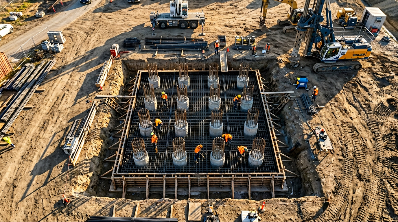
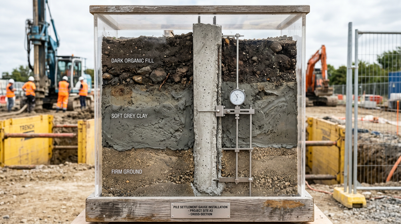
Recent fill over soft clay. New industrial estates on the Western Melbourne fringe — Truganina, Tarneit, Laverton North — often sit on 1–3 m of engineered fill placed over soft-to-medium-stiff alluvial clay. The clay consolidates under the weight of the fill for years after placement. Piles driven through this profile experience significant NSF.
-
Deep cohesive layers beneath new surcharge. Port of Melbourne, Geelong waterfront, Fisherman’s Bend — places where historic reclamation fill has been placed over marine silts and clays that are still consolidating. Any new pile on these sites inherits the residual consolidation.
-
Pile groups in soft ground. Driven pile groups in soft clay actually cause consolidation in the ground between the piles, through remoulding of the clay during driving. Piles around the perimeter of a group experience NSF from this process.
-
Dewatering-induced settlement. Any site where groundwater has been lowered — permanent or temporary. The increased effective stress consolidates the ground. Happens constantly during Melbourne CBD basement construction.
-
Adjacent surcharge loads. A new embankment or stockpile beside existing piles induces settlement of the ground around those piles. NSF builds up on the piles over weeks to months.
Quantifying the downdrag load
AS 2159:2009 Clause 4.4.2 requires downdrag to be considered in pile design wherever the ground is actively consolidating or subject to future settlement. The standard design approach is the β-method — same as positive shaft friction, but in the opposite direction:
Negative shaft friction f_s = K_s · σ'_v · tan(δ) = β · σ'_v
where σ’_v is the vertical effective stress at depth z, and β is a coefficient typically in the range:
- Soft clay: 0.15–0.25
- Medium clay: 0.25–0.40
- Sand (fill): 0.30–0.55
- Stiff clay: 0.25–0.35
Integrating from ground surface to the neutral plane depth gives the total downdrag force per pile.
Finding the neutral plane
Fellenius (1984, 2004) showed that the neutral plane location depends on relative pile-soil settlement, which in turn depends on:
- Pile stiffness (axial load-displacement behaviour)
- Soil stiffness at each depth
- Consolidation rate of each layer
- Time after pile installation
For practical design, the neutral plane is often approximated as being at:
- 70–90% of the pile length in sands.
- 60–80% of the pile length in mixed soils.
- 60–75% of the pile length in soft clays.
More rigorously, Fellenius’s unified method iterates pile load, soil settlement and capacity distribution until compatible. Commercial software (UNIPILE, GROUP) handles this automatically.
Design approaches — four options, pick one
Option 1 — Include downdrag as a permanent load
The conservative approach: treat the full downdrag force as an additional permanent compressive load on the pile. Size the pile for structural load + downdrag, then verify the geotechnical capacity below the neutral plane is adequate.
This works but can be very conservative. A typical Western Melbourne industrial pile with 15 m of fill + clay over firm stratum might see 200–500 kN of downdrag per pile — which easily doubles the effective load and pushes pile diameters 100–150 mm larger than they’d otherwise need to be.
Option 2 — Fellenius’s “neutral plane” analysis
Under Fellenius’s method, the downdrag above the neutral plane is balanced by positive shaft friction below it at long-term equilibrium. The pile’s geotechnical capacity is therefore checked at the neutral plane under the structural load only, not the structural load + downdrag. The downdrag imposes a compressive stress on the pile structure, but it does not require additional geotechnical capacity in the pile below the neutral plane.
This is the modern best-practice approach and is accepted in AS 2159 Clause 4.4.2 commentary and AS 5100.3 Clause 10.8 for bridges.
The pile structural section must still be checked for the peak axial load at the neutral plane (structural + downdrag combined).
Option 3 — Bitumen coating (drag reduction)
The downdrag force can be reduced by up to ~90% by applying a soft coating to the pile shaft in the settling zone. Hot-applied bitumen (1–5 mm thick) is the classical method, though modern high-elongation polymeric coatings are also available.
The coating allows relative slip between soil and pile with minimal shear resistance. It is particularly effective on precast concrete piles where the coating can be applied in the factory. For bored piles, coating is impractical except on the top segment (pre-applied to a sacrificial casing, which is later removed).
Option 4 — Isolate the pile from settlement (sleeve or casing)
An oversized permanent casing through the settling layer, with the annulus filled with pea gravel or other low-shear backfill. The pile sits inside the casing without touching it in the settling zone.
Works well for short (<5 m) settling layers; becomes expensive for deeper profiles. Also creates a potential water conduit that needs detailing.
What we do on site
For typical Melbourne industrial warehouse projects on fill-over-clay, our default is:
- Flag it at quote stage if the geotech shows recent fill, soft clay, or an active consolidation profile. We include a downdrag line-item in the estimate.
- Analyse under Fellenius neutral-plane method for the ultimate geotechnical check, and include the downdrag as a compressive load for the structural check on the pile section.
- Specify precast driven piles with bituminous coating where downdrag exceeds ~300 kN per pile. Factory-applied 3 mm hot bitumen at a marginal cost premium is cheaper than upsizing the pile.
- Install settlement monitoring points adjacent to selected piles during construction. Measured pile-head settlement vs surrounding ground settlement directly proves or disproves the design assumption.
Common pitfalls
- Ignoring downdrag on “compacted fill” sites. Engineered fill still consolidates, especially under its own weight in the first 1–2 years, and especially in summer-cycle reactive clay subgrades. Treat all fill-over-soft-ground as a potential downdrag case.
- Designing for ultimate with downdrag applied, then checking SLS without it. Settlement behaviour is governed by long-term effective stress, which includes the downdrag. Apply consistently.
- Over-conservative Option 1 designs with bitumen coating also specified. Double-counting the mitigation. Pick one.
- Failing to check the pile structural section for the neutral-plane peak. The neutral-plane load is the controlling axial load on the pile concrete. Design the longitudinal reinforcement to this, not the applied service load.
References
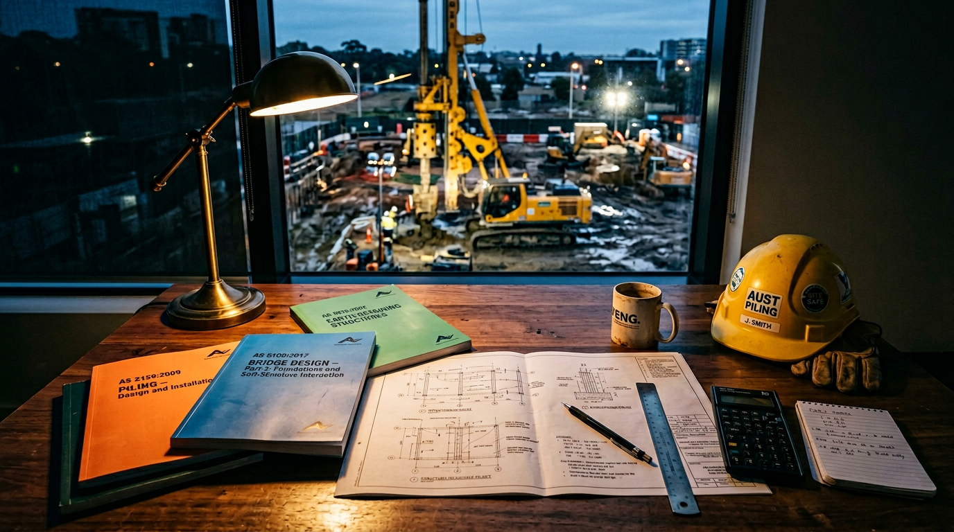
- Standards Australia, AS 2159:2009 Piling — Design and Installation.
- Standards Australia, AS 5100.3:2017 Bridge design — Foundations and soil-supporting structures.
- Fellenius B.H., Unified Design of Piled Foundations with Emphasis on Settlement Analysis, ASCE GSP 125, 2004.
- Fellenius B.H., Negative Skin Friction and Settlement of Piles, 2nd International Seminar, Pile Foundations, Nanyang Technological Institute, Singapore, 1984.
- Poulos H.G., Pile behaviour — Consequences of geological and construction imperfections, ASCE, 2005.
VIC PILING is a specialist piling contractor delivering tier-1 civil, energy, rail and commercial foundations across Victoria since 2016. Our principals bring 30+ years of combined design, installation and compliance experience under AS 2159, AS 5100 and AS 4678.