Every designer of a bridge pier, wind turbine base or tower column runs into the same temptation: “if a single pile carries 2,000 kN, then I need twelve piles to carry 24,000 kN”. The maths is satisfying. The answer is wrong.
Pile groups do not carry the sum of the single-pile capacities. Depending on pile spacing, ground type and loading direction, a pile group’s capacity can be anywhere from 120% of the sum-of-singles (rare) down to 50% (common). Its settlement for a given load is usually 3–10× that of a single pile. This article sets out why — and what practical numbers to use.
The three reasons a group behaves differently
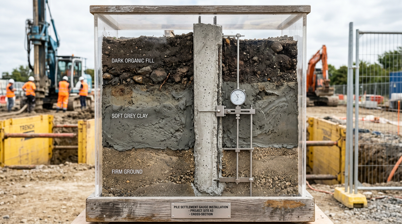
1. Stress field overlap. A single pile’s stress bulb extends roughly 3–5 pile diameters sideways at depth. Piles spaced closer than 6–8 diameters have overlapping stress fields — the soil between them is “double-stressed”. The soil yields earlier, the piles settle faster, and the effective shaft friction drops.
2. Shadowing (lateral loading). In lateral loading, the leading row of piles pushes soil forward; the trailing rows then find soil that’s already been pushed (and partly yielded). Each trailing row sees less soil resistance than the leading row.
3. Block failure mode. Close-spaced pile groups can fail as a single “block” — the group + enclosed soil moves together, and the perimeter shears around the block. When block failure is critical, group capacity is governed by the perimeter shear area (small), not the sum of individual pile shafts (large).
Group efficiency factor
The standard metric is group efficiency:
η = (capacity of group) / (sum of single-pile capacities)
Typical values for a vertical (axial compression) group:
| Pile spacing | Cohesive soil (clay) | Granular soil (sand) |
|---|---|---|
| 2.5d | 0.65–0.80 | 0.75–0.90 |
| 3.0d | 0.75–0.90 | 0.85–0.95 |
| 3.5d | 0.80–0.95 | 0.90–1.00 |
| 4.0d | 0.90–1.00 | 0.95–1.05 |
| 6.0d+ | ≈1.00 | ≈1.00–1.10 |
Sand often shows η ≥ 1.0 at 4–6d spacing because driven-pile installation densifies the soil between piles, increasing shaft friction. Installation-induced gain.
Clay always shows η ≤ 1.0 at close spacing. Cohesive strength doesn’t gain from installation — in fact, it loses from remoulding near driven piles.
Block failure — the lower-bound capacity
For cohesive soils, block failure sets a lower bound on group capacity. The failure mechanism is the perimeter of the pile block + enclosed soil, shearing as a monolith through the clay.
Q_block = 2 (B + L) × D × c_u_avg + (B × L) × N_c × c_u_base
where B, L = block plan dimensions; D = block depth; c_u = undrained shear strength; N_c = bearing capacity factor (typically 9 for deep foundations).
The design group capacity is the minimum of:
- Sum of single-pile capacities × η (stress field), and
- Block failure capacity Q_block.
For cohesive soils, block failure often governs at close spacings (< 3d). Check both.
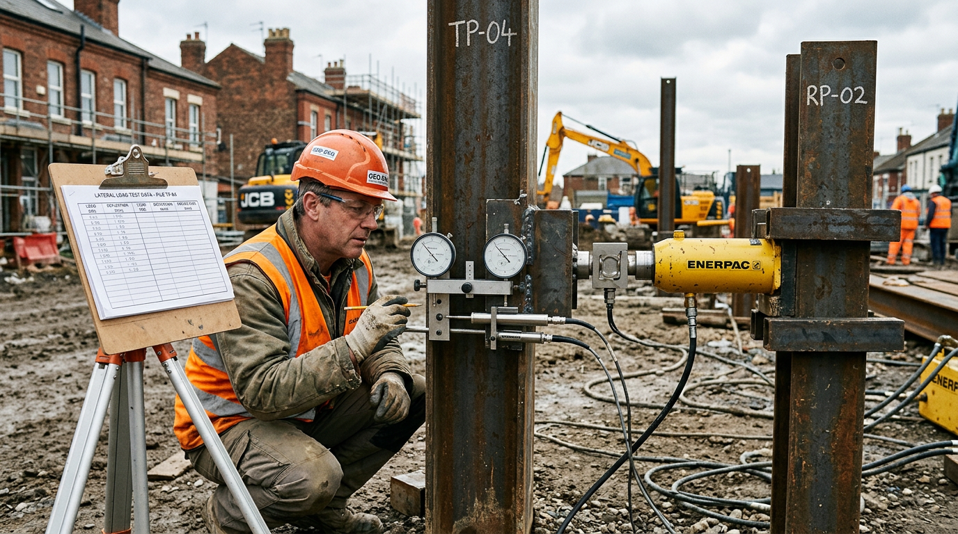
Lateral group efficiency — the more dangerous case
Lateral loading is where groups underperform most dramatically. The leading row carries disproportionate load; the trailing rows struggle. A 2×3 pile group loaded laterally at 3d spacing carries approximately:
- Leading row piles: 85–95% of single-pile capacity.
- Middle row piles: 40–60% of single-pile capacity.
- Trailing row piles: 30–45% of single-pile capacity.
Typical p-multipliers (factor applied to single-pile p–y curves) from Reese et al. (2006) and Brown et al. (1988):
| Spacing | Leading row | Second row | Third row | Trailing row |
|---|---|---|---|---|
| 3d | 0.8 | 0.4 | 0.3 | 0.3 |
| 4d | 0.9 | 0.5 | 0.4 | 0.4 |
| 5d | 1.0 | 0.7 | 0.6 | 0.6 |
| 6d | 1.0 | 0.8 | 0.8 | 0.8 |
The leading-row share increases if the cap is stiff, which is normally the case.
See our lateral pile analysis article for the full p–y method.
Group settlement — the real killer
Group efficiency relates to capacity. The more insidious effect is on settlement. Even at 6d spacing where capacity is ~unity, the group settlement for a given working load is typically:
- 3–5× the single-pile settlement for end-bearing piles.
- 5–10× for friction piles.
Why? Because the “zone of influence” (the soil volume that takes the load) extends much deeper below a group than below a single pile. Traditional analysis: assume the group load is applied as an equivalent raft at 2/3 of pile length and distribute the load at 1V:2H through deeper strata. Calculate settlement of the equivalent raft using elastic or consolidation methods.
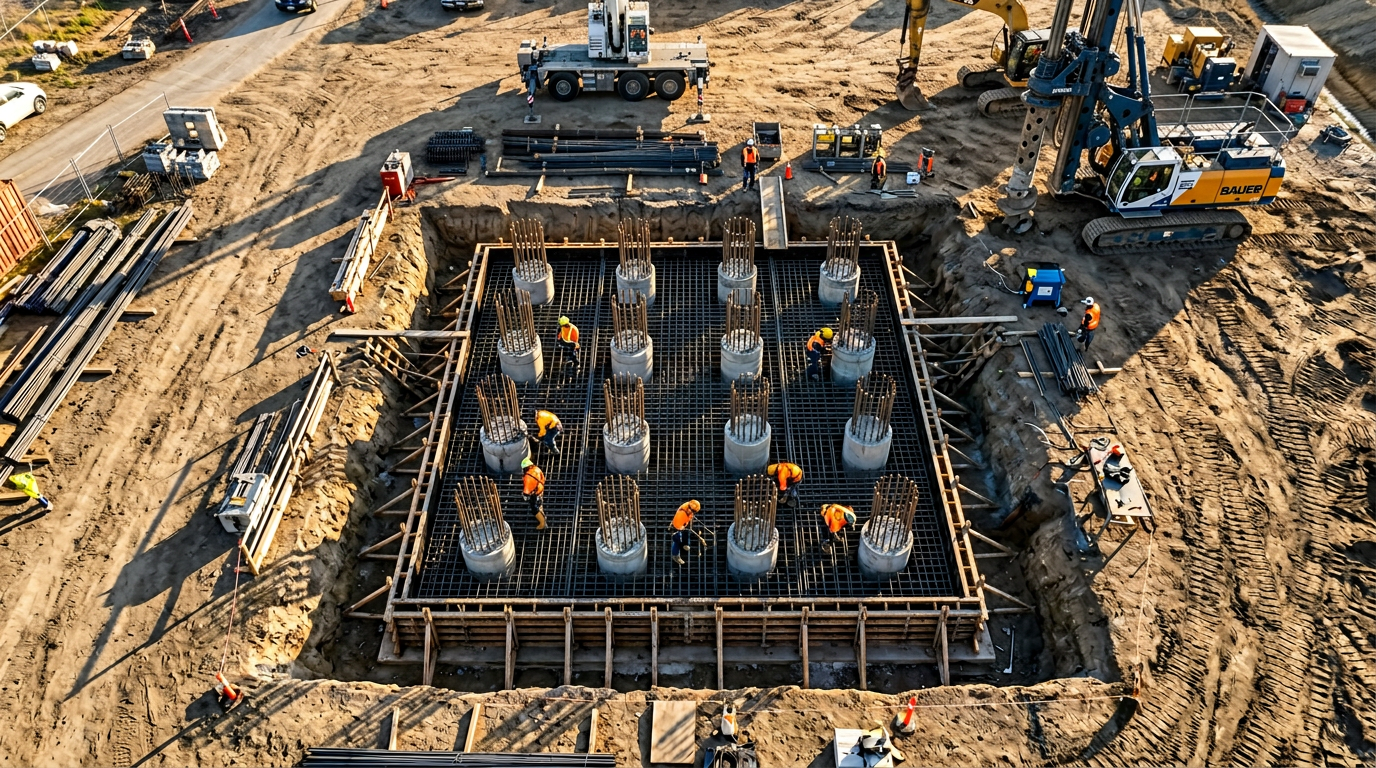
For a 6×6 pile group (36 piles, 3d spacing, 20 m long) in stiff-to-very-stiff clay, expected settlement at the working load might be 30–50 mm — while a single pile at the same unit shaft stress would settle only 4–8 mm.
Group settlement typically governs serviceability-critical designs: tower buildings, bridge piers, data centres, precision-manufacturing facilities.
How we apply this in practice
At design stage:
- Run a single-pile analysis to establish axial capacity and expected settlement.
- Determine group efficiency for axial compression using table values or project-specific values from a commercial program (GROUP, PLAXIS).
- Check block failure on cohesive sites.
- Determine group settlement using the equivalent raft method, or via continuum analysis in PLAXIS / FLAC.
- For laterally-loaded groups — apply p-multipliers per row, run a full coupled pile-group analysis.
- Verify with a test program — typically a single-pile static test plus a group settlement monitoring program during construction.
Specification — what we write
For a typical bridge pier on a 3×3 group of 900 mm piles:
- Pile spacing: 3.0 m centre-to-centre (3.3d). This is generally the minimum we recommend for driven concrete piles.
- Capacity check per AS 5100.3 Clause 10.7:
- Single pile ultimate capacity: 6,500 kN.
- Group efficiency (sand, 3.3d): 0.95.
- Block failure: not governing (sand).
- Allowable group load at ULS: 9 × 6,500 × 0.95 / γ_g = 46,700 / 1.5 ≈ 31,000 kN.
- Settlement at SLS: 25 mm maximum (project-specific; bridge expansion joints govern).
- Lateral check — full p–y group analysis with p-multipliers.
- Cap: reinforced concrete, designed to AS 3600 Chapter 13 (pile-cap design), see pile-to-pilecap connection.
Common mistakes
- Using η = 1.0 and moving on. Even at 4d spacing, efficiency is rarely 1.0 in clay. It is never safe in laterally-loaded groups.
- Ignoring block failure in stiff-clay groups. The block mode governs close-spaced cohesive groups.
- Calculating “group capacity” but forgetting settlement. The group may have adequate ULS capacity but fail serviceability at working load.
- No p-multipliers on lateral-group analysis. The commercial software does not apply them by default — you have to specify them row-by-row.
- Assuming the pile cap distributes load equally. Stiff caps give the leading row most of the lateral load. Design each pile for the peak row load, not the average.
References
- Poulos H.G., Pile Behaviour — Consequences of Geological and Construction Imperfections, ASCE, 2005.
- Reese L.C., Isenhower W.M., Wang S.-T., Analysis and Design of Shallow and Deep Foundations, Wiley, 2006.
- Brown D.A., Morrison C., Reese L.C., Lateral Load Behavior of Pile Group in Sand, Journal of Geotechnical Engineering, ASCE, 1988.
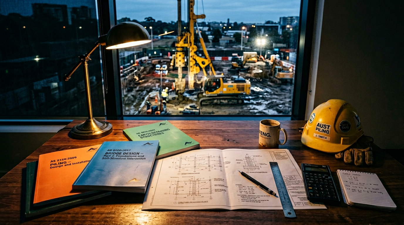
- Standards Australia, AS 5100.3:2017 Bridge design — Foundations and soil-supporting structures.
- Fleming W.G.K. et al., Piling Engineering, 3rd ed., Taylor & Francis, 2009.
VIC PILING is a specialist piling contractor delivering tier-1 civil, energy, rail and commercial foundations across Victoria since 2016. Our principals bring 30+ years of combined design, installation and compliance experience under AS 2159, AS 5100 and AS 4678.