Helical screw piles are unique among piling systems because their installation is a test. Every turn of the drive head measures the soil resistance at the helical plate’s depth. That continuous measurement is why a well-installed screw pile has some of the most auditable capacity records in the industry — and why the torque-to-capacity correlation has been adopted into AS 2159 Section 8 as a recognised verification method.
But torque is not capacity. It is a proxy for capacity, and the proxy has limits. Here is the engineer’s guide to when torque-only verification is enough, and when it is not.
1. Where the torque-capacity relationship came from
The idea traces back to Hoyt & Clemence (1989) and was formalised commercially in the 1990s. The empirical observation:
The ultimate axial capacity of a helical pile is approximately proportional to the installation torque at final depth, multiplied by a dimensionless coefficient, Kt.
Mathematically:
Q_ult ≈ Kt × TWhere:
Q_ult= ultimate axial capacity (kN)T= average installation torque over the last ~3 pile diameters (kN·m)Kt= torque correlation factor (dimension 1/m)
Typical Kt values from industry practice (Perko, 2009; CFEM 2006):
- Small-shaft piles (shaft diameter ≤ 89 mm): Kt = 10 to 12 m⁻¹
- Medium-shaft piles (114–168 mm): Kt = 8 to 10 m⁻¹
- Large-shaft piles (≥ 219 mm, our typical range up to 1,050 mm): Kt = 5 to 9 m⁻¹
- Round-shaft composite piles: lower Kt, typically 5 to 7 m⁻¹
Larger-diameter piles have more shaft friction contributing to the installation torque, so Kt decreases with diameter.
2. How AS 2159 treats it
AS 2159:2009 Section 8 permits torque correlation as a means of installation verification when the Kt has been established by on-site load testing or from documented local experience with the specific pile type, soil and installation equipment.
This is important. A manufacturer’s published Kt from US screw-pile experience is not automatically applicable to Victorian ground and Victorian installation equipment. The Standard expects you to either:
- Run one or more static load tests at the start of a project to establish the site-specific Kt, then use torque verification on the remaining piles; or
- Rely on documented local experience — which requires the designer to hold their own Kt records for the specific combination of pile type, soil profile and rig.
Without one of these, torque verification alone does not satisfy AS 2159.
3. How we run torque verification on a project
Our standard protocol:
3.1 Pre-installation
- Design the pile schedule assuming a conservative Kt from literature (e.g. 7 m⁻¹ for large-shaft piles).
- Nominate two test piles at representative locations — one in the lowest-strength boring, one in typical ground.
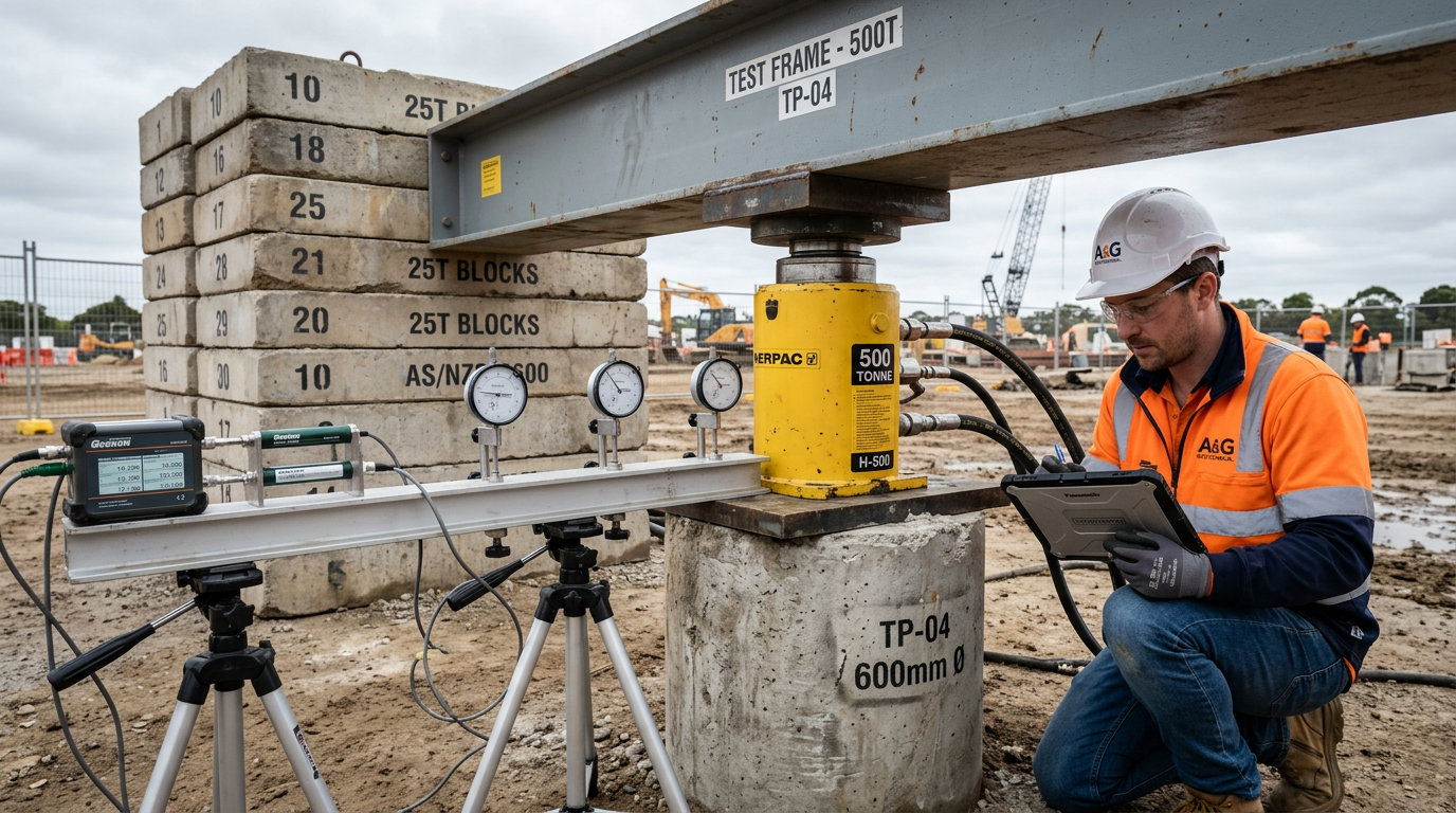
- Plan a static or Statnamic test on each test pile.
3.2 Test pile installation
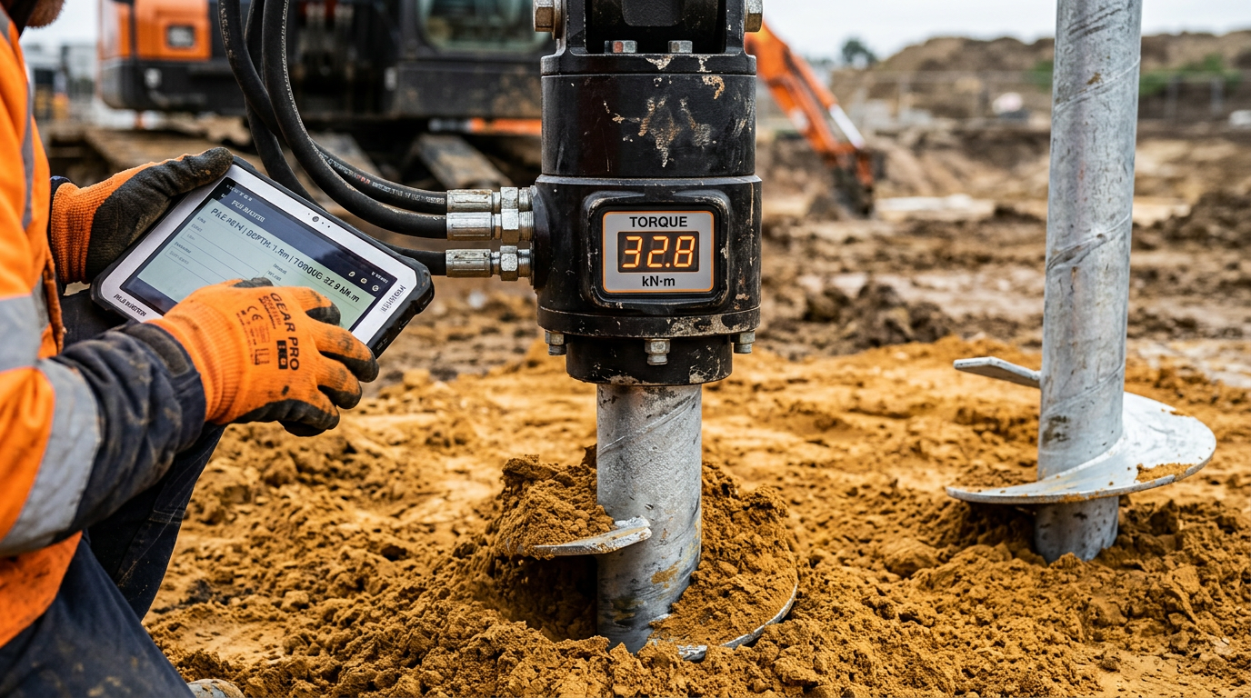
- Install each test pile with continuous torque logging — every 250 mm of advance.
- Record final-depth torque (average over the last three pile diameters).
- Allow set-up time (typically 24–72 h for cohesive soils).
- Execute the load test to failure or proof load.
3.3 Kt back-calculation
Kt_site = Q_ult_measured / T_avg_finalIf Kt_site is within 20% of the literature value, proceed with torque verification on production piles using Kt_site. If it is outside that range, investigate — the test may have been on anomalous ground, or the pile-soil system is different from assumed.
3.4 Production pile verification
Every production pile installed with continuous torque logging. Acceptance:
T_required = Q_design / Kt_sitePiles achieving T_required at or before design depth are accepted. Piles that do not are either driven deeper, or escalated to a re-test.
4. What torque verification misses
Torque is a good proxy for capacity — but it does not capture:
4.1 Long-term set-up or relaxation
In sensitive clays, torque at installation may be higher than long-term capacity (creep) or lower (set-up). A load test 24–72 h after install captures this; instantaneous torque does not.
4.2 Shaft friction below the final helix
Long screw piles in deep strata develop shaft friction above the helix. Torque measures resistance at the helix, not along the shaft. A 15 m pile with most of its capacity in shaft friction will not torque proportionally to total capacity — you need a side-friction correction or a supplementary test.
4.3 Pile head condition
A pile with a damaged or misaligned head, or with inadequate connection to the cap, cannot carry design load even if the torque says it can.
4.4 Corrosion and durability
Torque says nothing about whether the coating survived installation. A galvanised screw pile with a scratched coating in aggressive ground will fail on durability long before it fails on capacity. Durability is a visual inspection at acceptance, not a torque check.
5. When torque verification alone is not enough
Four project types where we always specify a physical load test in addition to torque:
- Piles supporting critical structures — bridge piers, process platforms, tanks. The consequence of one miscorrelated Kt is not worth the saving.
- Aggressive or unusual ground — acid-sulfate soils, organic soils, saline marine clays. Published Kt values were not derived in these conditions.
- Very long piles (≥ 25 m) where shaft friction is a significant fraction of capacity.
- First project for a new pile manufacturer or new rig — you have no local Kt history.
6. Equipment — what a good installation record looks like
A defensible torque record requires:
- Calibrated torque sensor at the drive head — ideally in-line with the drive shaft, not derived from hydraulic pressure alone.
- Digital logger recording torque, depth and rotation rate every 250 mm.
- Calibration certificate issued within 12 months of the installation.
- Standardised rotation rate — torque readings are rate-dependent. If the rig slows at depth because of fatigue, the reading drifts.
Older rigs that report only hydraulic pressure need a hydraulic-to-torque conversion factor that is rig-specific and often poorly characterised. If an audit traces a torque record back to “hydraulic pressure on gauge 3”, the record is weak.
7. Reporting — what a principal contractor expects
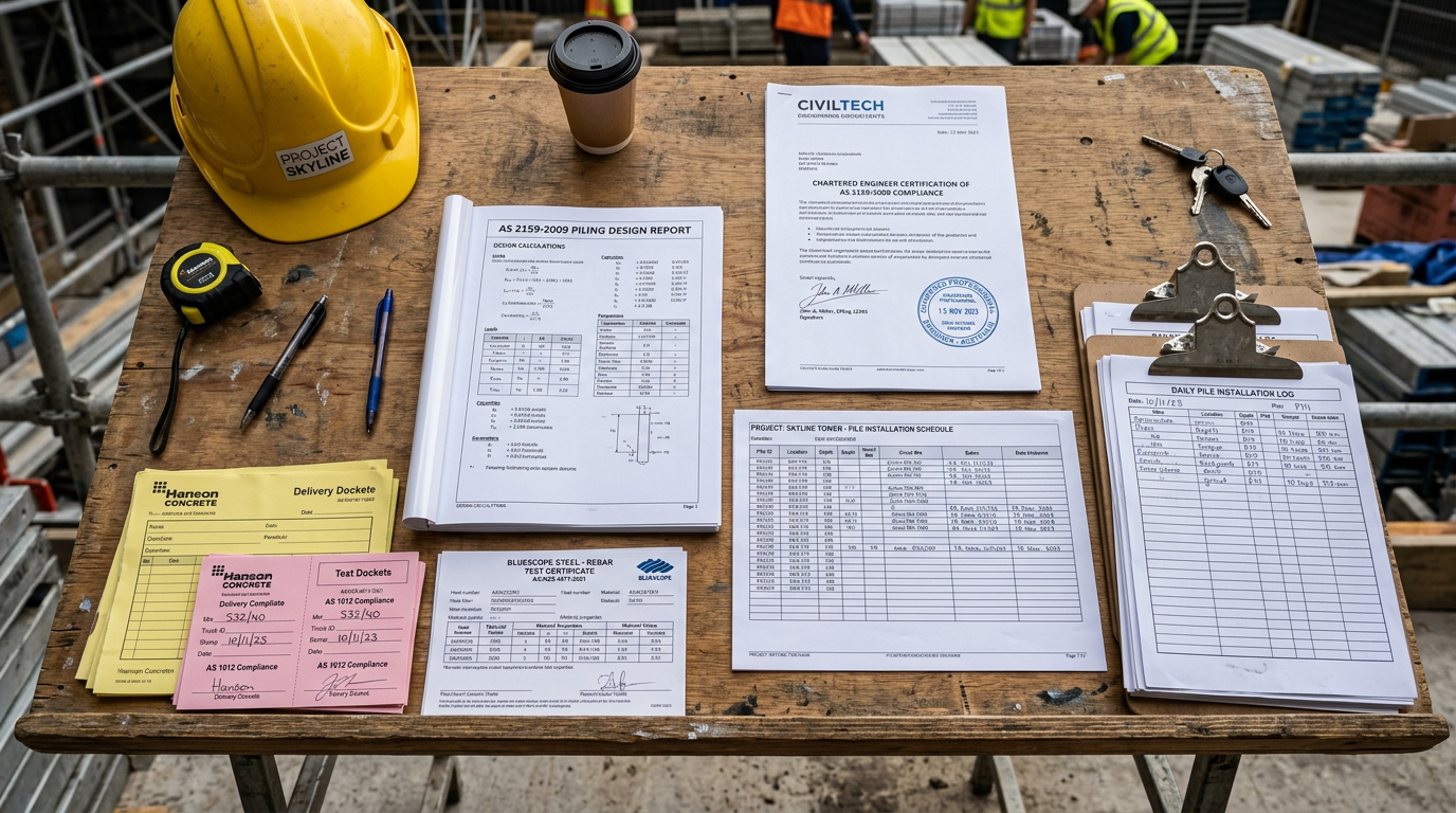
A defensible pile pack for each production pile on a torque-verified project includes:
- Pile ID and location.
- Time of installation.
- Operator name.
- Rig ID and sensor calibration reference.
- Torque vs depth plot.
- Final-depth average torque over last three pile diameters.
- Calculated capacity against design, with Kt referenced.
- Pile head elevation and cut-off record.
- Visual inspection note on coating integrity.
Every pile. On handover. Rolled into the AS 2159 compliance pack.
8. A word on “design-and-install by torque alone”
Some contractors quote projects where they will install piles to a design torque without any geotechnical investigation or load test. This is outside AS 2159 practice. Without a geotech, there is no design capacity to aim for. Without a test, the Kt is a guess. The fact that a pile reached a nominated torque means nothing if the Kt was wrong.
If a tender is asking for design-and-install-by-torque with no site investigation and no load test, the principal is asking for risk to be carried by the contractor without information. A sensible contractor declines, or prices the unknown aggressively, or insists on a test programme as a pre-condition.
9. Our standard torque-verification delivery
On a screw pile project we:
- Install test piles at representative locations with full torque logging.
- Execute a load-test programme against AS 2159 Section 8.
- Back-calculate site-specific Kt with an engineer’s sign-off.
- Install production piles with continuous torque logging.
- Produce a per-pile record with capacity demonstration.
- Issue a chartered engineer certification against AS 2159 at close-out.
That is the package that converts torque verification from “what the industry does” into “what the auditor accepts.”
Need a torque-verification scheme on your next project? Send the pile schedule and geotech to info@vicpiling.com.au or call 0466 651 881.
References
- Standards Australia, AS 2159:2009 — Piling: Design and Installation, Sections 5 & 8.
- Perko, H. A., Helical Piles: A Practical Guide to Design and Installation, Wiley, 2009.
- ICC Evaluation Service, AC358 — Acceptance Criteria for Helical Systems and Devices, 2018.
- Hubbell / CHANCE, Technical Design Manual for Helical Foundations and Tiebacks, Edition 4, 2014.
- Ghaly, A. & Hanna, A., “Ultimate pullout resistance of single vertical anchors”, Canadian Geotechnical Journal, 31(5), 1994, pp. 661–672.
Article technically reviewed by a chartered civil/geotechnical engineer (CPEng, MIEAust).
VIC PILING is a specialist piling contractor delivering tier-1 civil, energy, rail and commercial foundations across Victoria since 2016. Our principals bring 30+ years of combined design, installation and compliance experience under AS 2159, AS 5100 and AS 4678.