Pile load testing is not a box-ticking exercise. Done properly, it changes the design. AS 2159 Section 8 lets you raise the geotechnical strength reduction factor Φg — and therefore the design capacity — as soon as you back the design with measured pile performance. Done poorly, a load test adds cost and gives you a number that nobody trusts.
Here is the working engineer’s view of the four test methods and when to use each.
1. Static load test — the reference standard
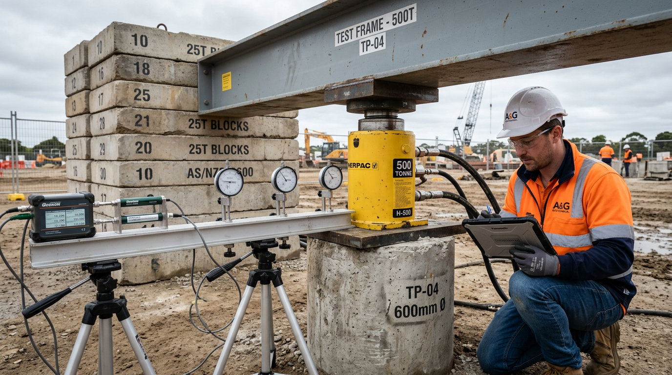
A static test applies load to the pile head with a hydraulic jack and measures displacement against time. Reaction is provided either by kentledge (a stack of concrete weights) or by reaction piles.
Best for: verifying compression capacity on production piles for critical or high-consequence works. Bridge piers, long-span buildings, marine structures.
What it measures: head settlement under incremental, sustained load. You get a load–settlement curve that is the ground truth for axial capacity.
Cost and time: the most expensive method — roughly $30k to $120k per test in Australia depending on load. Takes 24–72 hours on site including setup.
Rigging options:
- Maintained load test (MLT) — load held at each increment until creep stabilises. Best for characterising service behaviour.
- Constant rate of penetration (CRP) — pile displaced at a fixed rate while load is logged. Useful for finding ultimate failure quickly.
- Quick test (per AS 2159 Appendix A3) — incremental loading with short hold times. The most common production test.
What unlocks it in design: Φt up to 0.85–0.90 for static tests on production piles. The test reduction factor sits in AS 2159 Table 4.3.2.
2. Dynamic load test (PDA — Pile Driving Analyzer)
A high-strain dynamic test drops a weight onto the pile head (or uses the driving hammer) while strain gauges and accelerometers record the stress wave travelling down the shaft and reflecting off the base. The data is analysed with CAPWAP software to back-calculate shaft friction, end-bearing and pile integrity.
Best for: driven piles and restrike testing. Increasingly used on bored piers once concrete strength is adequate (typically 21 days).
What it measures: ultimate capacity mobilised during the impact event, distribution of shaft resistance along the shaft, and pile integrity.
Cost and time: $3k to $8k per test, typically 30 minutes per pile. You can test 10–20 piles per day on a production job.
Strengths: cheap per test, allows large test populations, gives shaft-resistance distribution.
Weaknesses: the impact event is short. For soft clay and creep-sensitive ground, dynamic capacity can differ from long-term static capacity. AS 2159 acknowledges this with a lower Φt.
What unlocks it in design: Φt up to 0.70–0.80 on typical soils. Lower on creep-sensitive ground.
3. Osterberg cell (O-cell) / bi-directional load test
A bi-directional test casts an expandable hydraulic cell (the Osterberg cell or one of several newer equivalents) into the pile shaft at a pre-determined depth. When pressurised, the cell pushes the upper portion of the pile upward and the lower portion downward simultaneously. The ground resists in both directions, and you measure both.
Best for:
- Very high-capacity piles (≥ 30 MN) where kentledge is impractical.
- Offshore or marine piles where reaction piles are not feasible.
- Bridge piers, LNG tanks, tall-building foundations, windfarm monopiles.
What it measures: shaft friction above the cell, combined shaft friction + end-bearing below the cell.
Cost and time: $80k–$300k per test including cell, instrumentation and analysis. Must be planned at design stage — the cell is cast into the pile.
The trick: the test only stops when one side of the pile fails. If shaft-above fails before base-and-shaft-below, you do not get ultimate end-bearing capacity. Design the test so the planned failure mode is the one you care about.
What unlocks it in design: Φt equivalent to a full-scale static test, but on piles that no kentledge could reach.
4. Pile integrity test (low-strain / sonic echo)
Not a capacity test, but worth mentioning because it is often confused with one. A small hammer taps the pile head and an accelerometer records the stress wave reflection. Defects (necks, voids, inclusions) show up as reflections before the base.
Best for: quality assurance on bored and CFA piles. Cheap and fast enough to run on 100% of piles.
What it measures: pile length and integrity of the shaft. Does not measure capacity.
Cost and time: $150–$400 per pile, 5 minutes per pile.
Complement: pair with cross-hole sonic logging (CSL) for large-diameter piers where tubes have been cast in — gives a higher-resolution defect map.
5. When to specify what — a practical decision guide
| Project type | Primary test | Secondary test |
|---|---|---|
| Residential slab on screw piles | Torque verification only | — |
| Commercial bored piers (≤ 2 MN) | PDA on 5–10% of piles | Integrity on 100% |
| Bridge pier, ≤ 10 MN | Static MLT on working load + 100% (proof) on 2 piles | PDA on 10% |
| High-rise bored pier, ≥ 30 MN | Osterberg bi-directional on 1 working pile | PDA on 10% |
| Offshore monopile | Bi-directional or instrumented restrike | — |
| Tension piles (wind, transmission) | Static tension pull test on 2 piles | Integrity on 100% |
6. What separates a useful test from a waste of money
Four things, in priority order:
- Test to failure or proof load, not just working load. A test that stops at working load tells you nothing you did not already assume. The value of the test is knowing where the pile fails.
- Instrument the shaft. Strain gauges at multiple levels — top, mid-shaft, base — give you shaft-resistance distribution. Without them, you have a single load–settlement curve and no insight into how the pile is carrying the load.
- Pick the pile deliberately. A test pile on the stiffest boring in the site tells you the upper-bound case. Pick the borehole where the geotechnical parameters were least favourable.
- Tie the result back to the design. The design capacity for every other pile on site is only as good as the test that verified it. Back-calculate shaft friction and end-bearing from the measured curve, and feed them into the remaining pile schedule.
7. Our standard test-planning process
On a new project with load testing specified, we:
- Review the geotech and the pile schedule.
- Nominate test pile locations in consultation with the geotech engineer.
- Pre-cast strain gauges at 3–5 levels for instrumented tests.
- Coordinate an accredited test engineer (NATA-registered).
- Deliver a test report that links measured capacity back to the AS 2159 design — with an updated capacity calculation for the remaining production piles.
That is the link that turns a load test into design value.
Planning a load test programme? Send the drawings and the geotechnical report to info@vicpiling.com.au or call 0466 651 881.
References
- Standards Australia, AS 2159:2009 — Piling: Design and Installation, Section 8 (Testing).
- ASTM D1143/D1143M-20, Standard Test Methods for Deep Foundation Elements Under Static Axial Compressive Load.
- ASTM D3689/D3689M-22, Standard Test Methods for Deep Foundations Under Static Axial Tensile Load.
- ASTM D3966/D3966M-22, Standard Test Methods for Deep Foundations Under Lateral Load.
- ASTM D4945-17, Standard Test Method for High-Strain Dynamic Testing of Deep Foundations.
- ASTM D8169/D8169M-18, Standard Test Methods for Deep Foundations Under Bi-Directional Static Axial Compressive Load.
- Fellenius, B. H., Basics of Foundation Design, Electronic Edition, 2023.
- Osterberg, J., “The Osterberg load test method for bored and driven piles”, FHWA-SA-94-035, 1994.
Article technically reviewed by a chartered civil/geotechnical engineer (CPEng, MIEAust).
VIC PILING is a specialist piling contractor delivering tier-1 civil, energy, rail and commercial foundations across Victoria since 2016. Our principals bring 30+ years of combined design, installation and compliance experience under AS 2159, AS 5100 and AS 4678.