A cofferdam is the cheapest way to work below the water table — provided it stays watertight. That caveat is doing most of the work in the sentence. A leaky cofferdam doubles your dewatering cost, triples your excavation time, and sometimes costs you the excavation entirely when the base blows out. Cofferdams that work are cofferdams that were designed properly.
Here is the working engineer’s view of sheet piling and cofferdam design in Victoria.
1. The cofferdam classification
There are three cofferdam configurations that cover 95% of Victorian work:
1.1 Simple rectangular cofferdam (≤ 6 m deep)
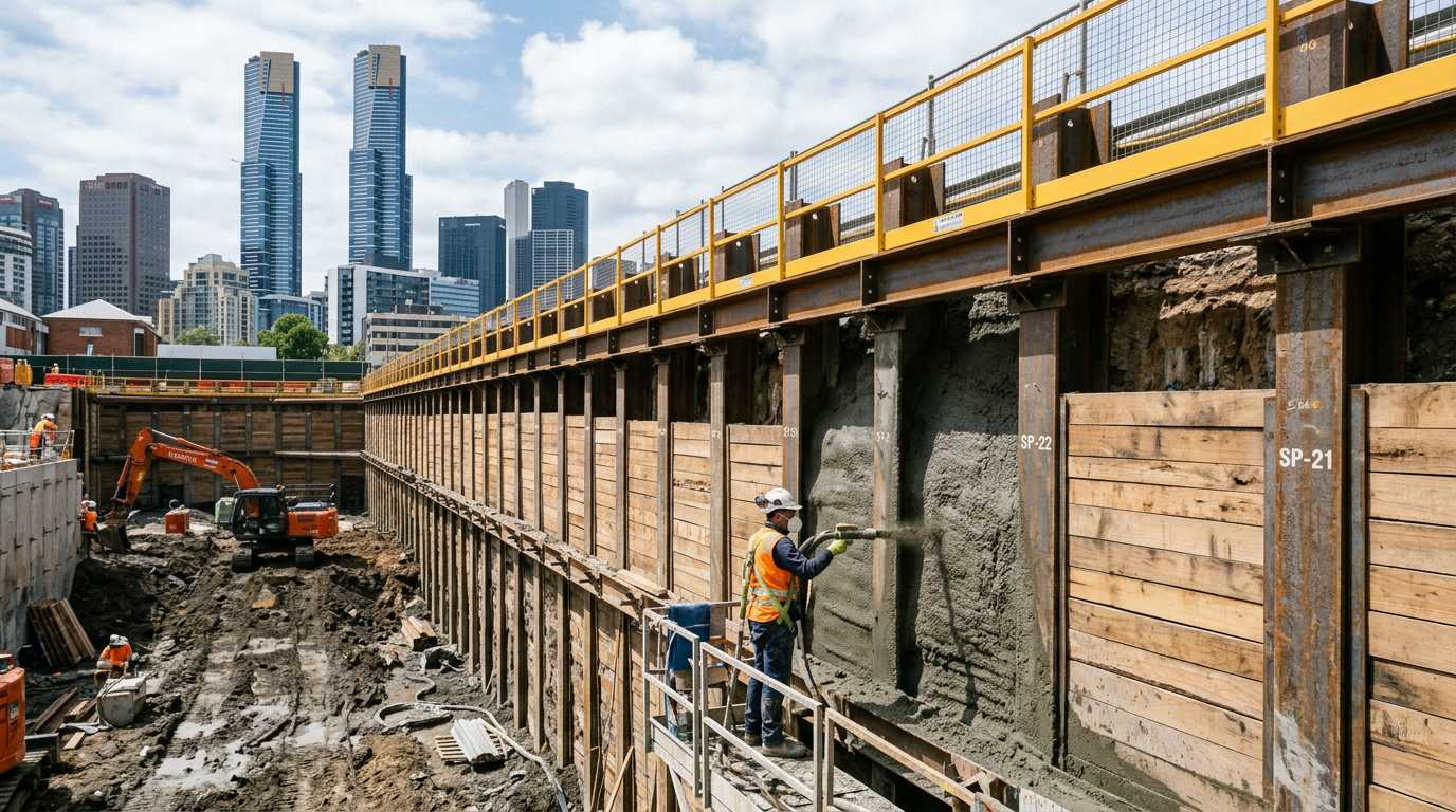
Four walls of interlocking sheet piles, braced internally with waler beams and strutting. Used for shaft constructions, sewer connections, and small bridge abutments.
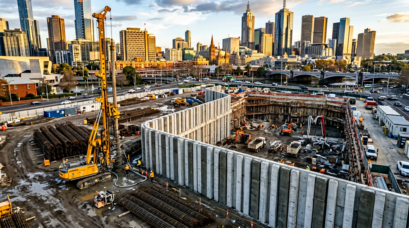
1.2 Circular / cellular cofferdam
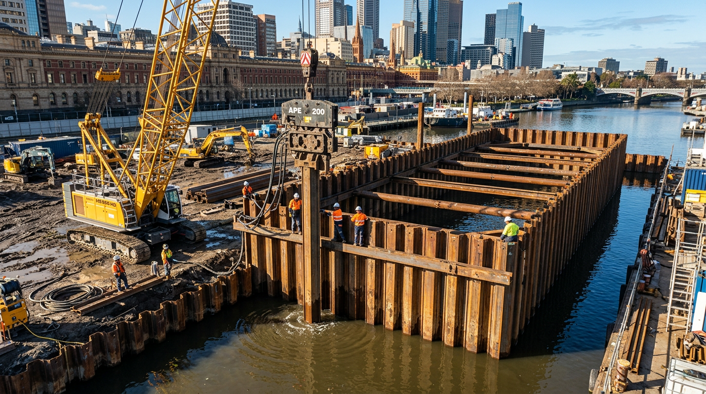
A closed ring of sheet piles, self-supporting in hoop tension. Used for larger plan areas where internal bracing would obstruct works. Common on river-crossing bridge piers.
1.3 Double-skin cofferdam
Two parallel rows of sheets filled with compacted granular material. Used for deep river crossings and marine works where hydrostatic pressure is very high. Rare in Victoria — more common in port projects interstate.
2. Selecting the sheet pile
The sheet pile section is chosen for three independent criteria — all three must pass:
- Bending capacity under the critical design case (usually the fully excavated, fully drawn-down internal condition).
- Interlock tension under the most severe driving or service case.
- Driveability into the specified ground.
Typical selections in Victoria:
| Cofferdam depth | Ground | Typical section (Larssen equivalent) |
|---|---|---|
| ≤ 4 m | Stiff clay, dense sand | AU14, AU16 |
| 4–8 m | Mixed alluvium, soft clay | AU18, AU20, AZ18 |
| 8–12 m | Stiff clay with groundwater | AZ26, AZ28 |
| 8–14 m river crossings | Alluvial sand with occasional cobbles | AZ30+, composite HZ/AZ sections |
For driveability into Melbourne’s basaltic terrain we almost always specify heavier sections than the bending alone would require — because refusal on cobbles in the upper 2 m is a higher-probability event than designers expect.
3. Sheet pile installation — the three methods
3.1 Vibratory drive
A hydraulic or electric vibratory hammer clamps to the pile head and liquefies the surrounding soil by high-frequency vibration. Fastest method. Works well in cohesionless soils.
- Watch out: noise and ground-borne vibration near heritage structures.
- Victorian rule of thumb: vibratory drive works down to medium-dense sand. Refuses on dense sand, cobbles or rock.
3.2 Impact drive
A traditional drop hammer or hydraulic hammer strikes the pile head. Slower, noisier, but drives harder ground.
- Watch out: pile-head damage. Use a driving cap and soft dolly.
3.3 Press-in / silent piler
Hydraulic reaction against previously installed piles pushes the next pile into the ground. Very quiet, minimal vibration. Slower than vibratory.
- Use it: near heritage structures, in residential areas, adjacent to sensitive equipment.
4. Dewatering — the part nobody wants to budget
A cofferdam is a bucket. The bucket only holds water out if the walls are watertight and the base is closed. The second condition is usually where cofferdams fail.
4.1 Base stability — the three checks
- Heave (effective stress failure of the passive zone). Excavate too deep and the passive soil inside the cofferdam has insufficient weight to resist the hydrostatic pressure below. The base heaves upward.
- Piping / hydraulic blow-out. Water finds a path under the toe of the sheets and upward through sand. Once piping starts, it accelerates.
- Plug uplift. The excavated plug (usually 1–2 m of soil between the final excavation level and a deeper impermeable layer) must weigh more than the hydrostatic uplift from below.
AS 4678 and Eurocode 7 both give methods for these checks. Skip any of them and the cofferdam can be hydraulically undone even with perfectly sealed walls.
4.2 Dewatering strategy
Four options, in increasing capability:
- Sump pumping from inside the cofferdam — cheapest, works if the base is tight and the inflow is slow.
- Wellpoints around the outside — drop the external water table below excavation level. Effective in sand.
- Deep wells — multiple deep extraction wells lowering the regional piezometric level. Necessary where upward gradients are high.
- Grouting or jet-grouting the base — when hydrostatic uplift cannot be controlled by pumping alone, a grouted base plug seals the bottom of the cofferdam.
4.3 The underwater-concrete option
For marine and river crossings, pouring an underwater tremie slab once the sheets are driven — sealing the cofferdam base before dewatering — is often the cheapest solution. The slab provides hydrostatic resistance, seals the toes of the sheets, and gives a working floor.
5. Internal bracing — walers and struts
Rectangular cofferdams need internal bracing. The bracing design has to cover:
- Differential surcharge loads — soil outside the cofferdam is rarely balanced on all four sides.
- Temperature load — a steel strut expands in summer and contracts in winter. A 30 m long strut can gain or lose 15 mm across a Victorian year.
- Surcharge from plant — a 40-tonne excavator sitting 2 m behind the sheets at one corner is a real load case.
- Wind load on exposed sheets above ground level.
The walers distribute point loads from the struts across the sheets. Misalign a waler by 50 mm and you load the sheets in torsion — a common reason single sheets “pop out” of interlock mid-excavation.
6. Interlock sealants
Interlock sealants turn driven sheets from “mostly watertight” to “watertight.” Two options:
- Factory-applied hydrophilic sealant — swells on contact with water. Forms a soft gasket in the interlock.
- On-site bitumen injection — applied post-drive. Cheaper but less reliable.
Sealants are cheap in absolute terms and transformative for cofferdam performance. On marine work or potable-water projects, specify factory-applied sealants.
7. The five reasons Victorian cofferdams leak
In our experience on Victorian jobs, leaks trace back to one of five root causes:
- Interlock declutching — the pile jumped out of interlock during drive because it hit an obstruction or rotated off verticality.
- Short piles — the sheet did not reach the required toe elevation, leaving a gap at the bottom.
- Base piping — designed excavation depth exceeded hydraulic safety margin.
- Damaged interlocks on previously used sheets — second-hand sheets with deformed interlocks do not seal.
- Corner detail — the junction between two sheet-pile walls is the most common leak path. Use corner sheets or welded close-offs.
Each of these is avoidable at design stage with ten minutes of thought.
8. Checklist before you drive the first sheet
- Geotechnical investigation with groundwater piezometer readings.
- Driveability analysis (GRLWEAP or equivalent) for the selected pile section.
- Base stability checks for heave, piping and plug uplift.
- Dewatering plan with pump capacity ≥ 2× design inflow.
- Bracing design with temperature, differential and surcharge load cases.
- Corner-detail sketches.
- Sealed interlocks specified where watertightness is critical.
- Monitoring plan — vibration, survey of adjacent structures, piezometer readings.
The one rule we work to
A cofferdam is an engineered structure in every respect. Treat it like a bucket and it behaves like a sieve. Treat it like a structure, design it properly, and it carries the programme.
Designing a cofferdam on your next Victorian project? Send the brief to info@vicpiling.com.au or call 0466 651 881.
References
- Standards Australia, AS 4678:2002 — Earth-Retaining Structures (reconfirmed 2021).
- Standards Australia, AS 3735:2001 — Concrete structures retaining liquids.
- Standards Australia, AS 2159:2009 — Piling: Design and Installation.
- US Steel, Steel Sheet Piling Design Manual, updated 1984 (still widely referenced).
- ArcelorMittal, Piling Handbook, 9th ed., 2016.
- CIRIA C760, Guidance on embedded retaining wall design, Gaba et al., 2017.
Article technically reviewed by a chartered civil/geotechnical engineer (CPEng, MIEAust).
VIC PILING is a specialist piling contractor delivering tier-1 civil, energy, rail and commercial foundations across Victoria since 2016. Our principals bring 30+ years of combined design, installation and compliance experience under AS 2159, AS 5100 and AS 4678.