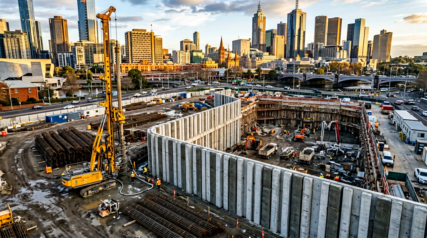
Soldier pile walls are the workhorse retention system for Melbourne basements, road widenings, rail corridor protection and general earthworks below the water table. They are flexible, fast, relatively cheap, and — when designed properly — will carry significant retained heights without movement. When designed badly, they transfer every millimetre of ground movement directly into the neighbour’s footings. The difference is almost entirely in the detailing.
Here is the engineer’s version of how we design them.
1. How a soldier pile wall actually works
A soldier pile wall is a discontinuous retention system. Vertical steel H-piles (soldiers) are driven or bored into the ground at spaced intervals. As excavation proceeds, horizontal lagging (timber, precast concrete panels or shotcrete) spans the gap between the flanges of adjacent soldiers.
The load path is:
- Retained soil pushes against the lagging.
- The lagging spans horizontally to the soldier flanges.
- The soldiers cantilever downward into the passive ground below the excavation, or back to an anchor / prop system above.
- A capping beam at the top distributes load between soldiers and resists out-of-plane rotation.
Every one of those four elements is a design decision.
2. The classification — AS 4678 Category
Under AS 4678, retention walls are Categorised 1, 2 or 3 based on the consequence of failure:
- Category 1 — low consequence of failure. Rural walls, minor retention on a flat site. Uncommon in Melbourne basement work.
- Category 2 — moderate consequence. Most commercial basement walls fall here.
- Category 3 — high consequence. Walls adjacent to public infrastructure, heritage structures, operating rail corridors, or where failure would be life-threatening.
The Category drives the factors of safety, the minimum monitoring regime, and the level of engineering review required. If a wall is next to a neighbour’s building, it is a Category 3 wall. This is not a grey area.
3. Soldier pile spacing
Typical soldier pile spacings in Melbourne:
- 2.0 m centres — short walls (≤ 4 m), lighter loads, timber lagging.
- 2.4 m centres — the most common commercial spacing.
- 3.0 m centres — larger soldiers (≥ 310 UC), precast panel lagging, stiffer design.
The spacing decision is a trade-off between:
- Pile cost (closer spacing = more piles, smaller sections)
- Lagging cost (wider spacing = larger lagging members)
- Lagging serviceability (wider spacing = more flex, more ground movement behind the wall)
For retention adjacent to a neighbour, keep spacing at 2.4 m or tighter.
4. Embedment below the excavation
The soldier pile must embed into the ground below the final excavation level to develop passive resistance. Minimum embedment is usually:
- 1.0 × retained height for cantilever walls in competent ground.
- 0.6–0.8 × retained height for walls with a single anchor or prop level.
- 0.5 × retained height for walls with multiple anchor levels.
A 4 m cantilever wall in stiff Melbourne clay typically needs 4 m of embedment below the excavation — a total pile length of 8 m for each soldier.
In soft clay or saturated fill, multiply by 1.5 or install an anchor to reduce the kick-out depth.
5. The capping beam — non-negotiable for Category 2 and 3
The capping beam is a reinforced concrete beam cast around the top of every soldier pile, tying them together. Its role:
- Distributes local surcharge loads between soldiers (a truck parked above one soldier is shared between its neighbours).
- Prevents individual soldier pile rotation about its long axis — a common failure mode on lightly braced walls.
- Provides a waterproofing line at the top of the wall to stop surface water running down behind the lagging.
- Carries any anchor or tie-back reaction into the pile heads.
A capping beam on a 2.4 m spaced soldier wall is typically a 600 × 600 mm reinforced concrete beam with 4N24 top and bottom. The soldier flanges must be welded or dowelled into the capping beam reinforcement — a loose cage around an unbonded pile is not a capping beam, it is a bit of concrete sitting on top of a wall.
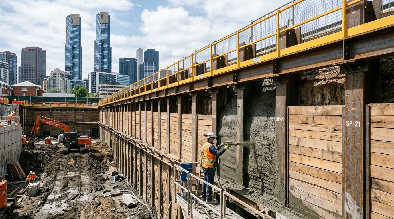
6. Lagging options
6.1 Timber lagging
- Best for: temporary walls, Category 1 and many Category 2 walls.
- Typical spec: 75 mm hardwood boards, treated, with drainage mat behind.
- Trade-off: degrades if permanent. Design for 18 months of service unless preservative-treated for permanence.
6.2 Precast concrete panel lagging
- Best for: permanent walls, wider soldier spacings.
- Typical spec: 150 mm reinforced concrete panels with drainage gap behind.
- Trade-off: heavy — needs crane installation. Tolerances on the soldier spacing become critical.
6.3 Shotcrete lagging
- Best for: permanent walls requiring a finished face, walls against an existing structure.
- Typical spec: 100–150 mm shotcrete over welded mesh, with drainage system behind.
- Trade-off: more expensive, but produces a monolithic permanent wall. Often paired with a waterproofing membrane and inner blockwork skin for basement walls.
6.4 Cast-in-situ concrete lagging
- Best for: permanent walls with architectural finish requirements.
- Trade-off: slowest option, but highest quality finish.
7. Drainage — the detail that kills walls
Water is the enemy of soldier pile walls. Hydrostatic pressure can double the design earth pressure. Every serious soldier pile wall must have:
- A drainage medium behind the lagging — geocomposite drainage mat is the default. Gravel drain for heavy-duty cases.
- Weep holes through the lagging or continuous drainage to a pipe at the toe.
- A sealed capping beam at the top — surface water must not enter the back face.
- A tile drain at the toe, discharged to stormwater or a sump pit.
On a Category 3 wall, the drainage detail is as engineered as the steel.
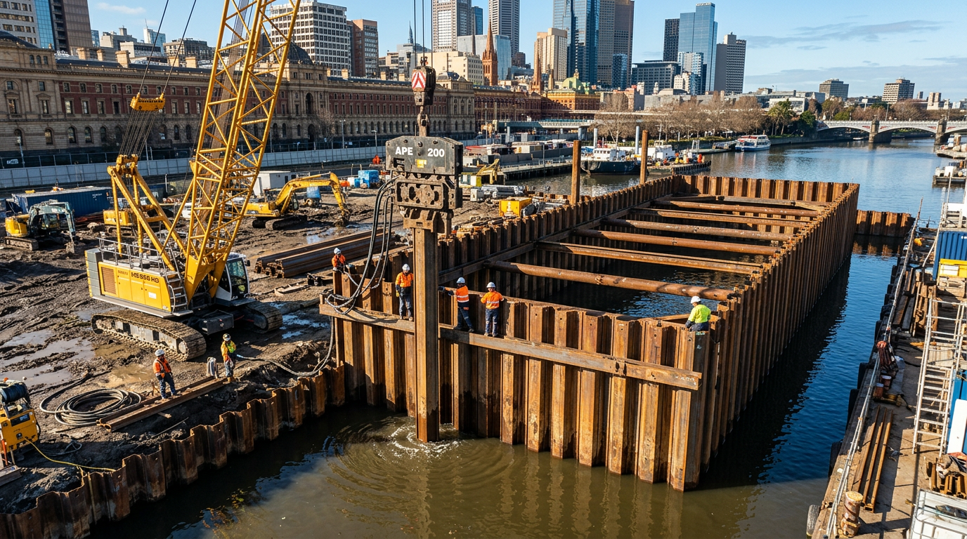
8. Anchors and props — when cantilever is not enough
For retained heights above 4–5 m, cantilever soldier piles become uneconomical. Anchors or props halve the pile bending moment and embedment.
Ground anchors (tiebacks)
Strand or bar anchors drilled back into the retained ground and stressed against the wall. Locked off at 80–100% of working load. Regrowth-tested at 125–150% of working load before acceptance.
Internal props
Steel tubes or beams spanning across the excavation, providing reaction between opposing walls. Simple, but obstruct the works.
Rakers
Inclined struts from the wall to a thrust block inside the excavation. Used where props cannot span and anchors cannot go beyond the boundary.
Anchor design must cover long-term creep, corrosion protection, and — for Category 3 walls — regular proof-testing through the life of the wall.
9. Monitoring — Category 2 and above
A Category 2 wall needs at minimum:
- Survey marks on the capping beam read weekly during excavation.
- Piezometers if groundwater is controlled by the wall.
A Category 3 wall needs all of the above plus:
- Inclinometers through or behind representative soldiers, read weekly during excavation and monthly through service.
- Strain gauges on anchor strands read after lock-off and at intervals through service.
- Trigger levels with defined response actions — amber triggers a review, red triggers stop-work and a design revisit.
10. The five most common detailing mistakes
- No capping beam or a disconnected one. Individual soldier piles rotate. The wall bulges.
- Drainage placed but discharged to nowhere. Water accumulates behind the wall anyway.
- Timber lagging specified for a permanent wall without preservative treatment. Ten years in, it rots. Soil pushes through and the wall fails unexpectedly.
- Soldiers installed out of vertical. Lagging fits badly, gaps open, soil washes out.
- Excavation exceeds design without reassessment. Contractor over-excavates by 500 mm to “get ahead”; passive resistance halves; wall deflects.
11. Our standard soldier-wall package
When we deliver a soldier pile retention to a head contractor, the package includes:
- Pile schedule with embedment, capacity and reinforcement.
- Capping beam drawings and reinforcement schedule.
- Anchor design (if applicable) with stressing records.
- Drainage plan.
- Installation records per soldier — drive or bore log, depth, verticality.
- Monitoring plan with trigger levels.
- Chartered engineer certification against AS 4678.
That is what converts a retention subcontract into an auditable lot under a tier-1 quality system.
Designing a retention wall on your next project? Send the drawings to info@vicpiling.com.au or call 0466 651 881.
References
- Standards Australia, AS 4678:2002 — Earth-Retaining Structures (reconfirmed 2021).
- Standards Australia, AS 2159:2009 — Piling: Design and Installation.
- CIRIA C760, Guidance on embedded retaining wall design, Gaba et al., 2017.
- Twine, D. & Roscoe, H., Temporary propping of deep excavations — guidance on design, CIRIA C517, 1999.
- FHWA-IF-99-015, Ground Anchors and Anchored Systems — Geotechnical Engineering Circular No. 4, 1999.
Article technically reviewed by a chartered civil/geotechnical engineer (CPEng, MIEAust).
VIC PILING is a specialist piling contractor delivering tier-1 civil, energy, rail and commercial foundations across Victoria since 2016. Our principals bring 30+ years of combined design, installation and compliance experience under AS 2159, AS 5100 and AS 4678.